Shader Graph Tutorial for Beginners: A Complete Introduction
Contents
- Introduction
- What is a shader?
- What is shader graph?
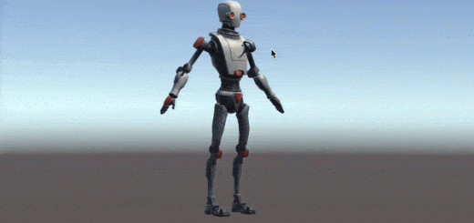
- Example effects that are made by Shader Graph
- How does a shader work?
- Fundamentals of the graphics rendering pipeline
- URP, HDRP and Default RP
- Setting up your scene for shader graph
- PBR Shader vs Unlit Shader
- Creating a shader with Shader Graph
- Shader graph editor
- Adding nodes and properties
- An example: the Earth Shader
Introduction
Shader development is an important part of game development. Nevertheless, it is not easy to understand shader programming since it is very different from classical programming. In this article, we aim to give a solid introduction to shader programming using Unity’s great tool Shader Graph. We will start with the basics of shader development and graphics pipeline. In the later parts of the article, we will learn several concepts that are used in shader programming by creating an Earth model using Shader Graph.
What is a shader?

A shader is a computer program that runs on GPU. Their main purpose is to determine the color of a pixel on the screen. A 3D model that is exported from a computer program such as Blender or Maya is a list of mathematical coordinates of the model’s vertices. These coordinates are taken by the shaders, their positions on the screen are calculated, the pixels on the screen are determined and finally, the colors of those pixels are returned. By developing your own shaders, you have full control over how the image on your screen will look like. Most independent game developers, who do not develop their own shaders, create games that are visually similar. Many game engines come with pre-defined shaders. These shaders have been developed for general use. In an interactive visual art branch such as computer game, it is of great importance for the image on the screen to create the desired psychological and physical effects. Therefore, shaders are of great importance to computer games. By learning to develop shaders, you can make computer games with both high performance and great visual quality.
In visual arts, shading objects properly is a crucial method to create the illusion of 3D on a 2D medium, like paper, movie theatre screen, or computer screen. Likewise, creating a perspective is also has great importance. If you cannot create perspective in the right way, realism will break and the image probably will seem ugly. The working and the aim of shaders are similar to painters. A painter projects a real-life object which is in 3D space onto a piece of paper then shade it in order to create the illusion of the 3D world. Lighting, material properties, and the imagination of the painter have great importance about how the image will be seen to its audience. Likewise, the aim of the graphics rendering pipeline is to simulate a virtual camera. Shaders are fundamental parts of this process. We simulate a virtual camera as well as the material and light interactions by using shaders.
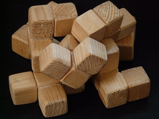
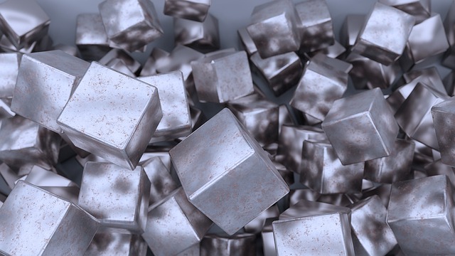
For instance, how do you distinguish between a wooden cube or a metal cube on a computer screen? In other words, what makes them distinguishable even though they have the same geometry?
Both objects seem very different because their interaction with light is quite different. This is the same for the objects in real-life also. If we want them to look different in our games, their material properties have to be different. This difference is created by the shaders.
What is shader graph?
Shader Graph is a visual shader development environment that is developed for Unity3D game engine. In the past, you had to write shader code in order to develop shaders in Unity. Most game developers ignore it up to an advanced level, since learning to code shaders is a painful process especially for those who do not have a formal education in computer science. GPU programming is quite different than conventional CPU programming. Because nearly all of the developers learn CPU programming first while they first started to coding.
Shader Graph presents a comfortable platform that gives you predefined nodes. You develop your shaders by connecting these nodes, and you do not have to have deep knowledge about GPU architecture and 3D Maths in order to develop them (nevertheless, it could be useful to learn 3D math and graphics pipeline for creating shaders).
You can see the results instantly while editing your shaders and this provides great convenience even if you are an experienced shader developer.
However, despite all these great features, Shader Graph has some restrictions. And sometimes, you may not directly create everything you want. But if you master on shader development, you surely find wisely ways to overcome these restrictions.
Example effects that are made by Shader Graph
If you are already following this blog, you probably know our shader graph tutorial series. For those who are new to this blog, here is the link for the complete list of our shader graph tutorials.
Let’s see a few examples that we created before in order to give some opinion for those who are new to shader development.
You can animate positions of vertices to create a flag animation:
You can make objects dissolve:
You can create a glass or a lens:
You can draw an outline on a basic mesh:
You can develop a teleport effect:
And finally, you can create an Earth Shader that we will create in this article as an example:
How does a shader work?
As mentioned above, shaders work on GPUs (Graphics Processing Units). A GPU is a device that is responsible to create images on a screen. Their architectures are quite different than the CPUs (Central Processing Units). They are designed to perform parallel operations, unlike CPUs. This means that they are much faster than CPUs to make computations that need parallel operations.
While developing shaders, we think as if we are writing the shader only for one pixel. Shaders are executed for each pixel, individually and simultaneously. None of the pixels can communicate with each other. Life of a shader is the time that passes during one frame. They forget what they did at the previous instant and run again for the new frame. We accept them as memoryless. If we want to store something, we do it by passing the data at that instant to RAM by communicating with the CPU.
Fundamentals of the graphics render pipeline
Shader development requires knowledge about computer hardware and how this hardware works. For a developer who does not have a formal computer science background, learning how things work could be a little bit painful, especially while writing shaders in Cg/HLSL. Fortunately, Shader Graph hides all these complex processes. In order to develop shaders in Shader Graph, you do not need to deep dive into these learn to hard topics. On the other hand, it is useful to learn a little bit about how things are drawn on the screen and this may help you to overcome restrictions that come with Shader Graph. This process is called graphics render pipeline. Let’s take a look.
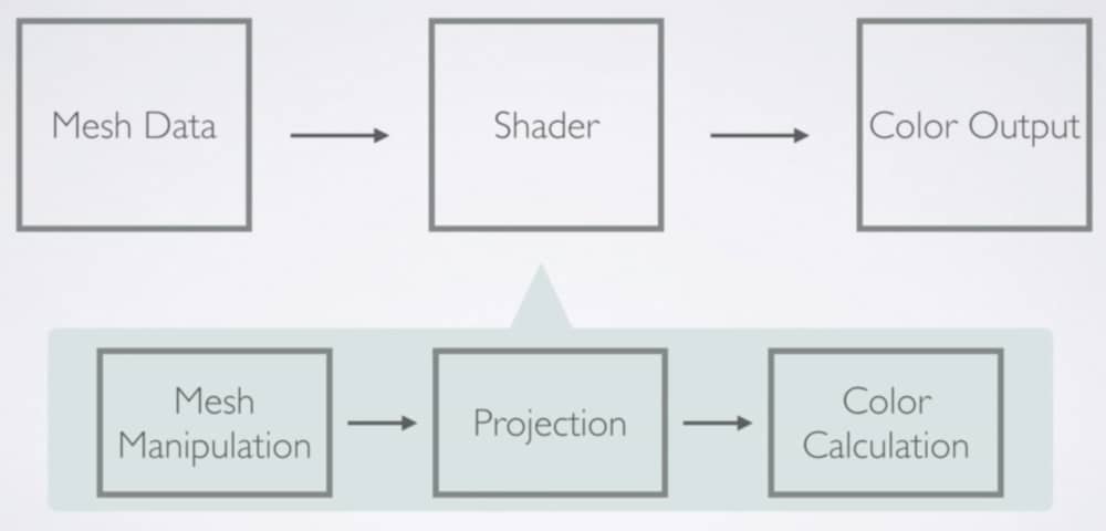
Mesh data, which may include positions of vertices, normals, UV coordinates, or color values, is taken by the shader. If you would like to manipulate any of the data that is stored in vertices, you have to do it before the GPU project them onto the screen. In Shader Graph, you are allowed to play with vertex position data. Thus, you do not have to restrict yourself with the exported geometry from the 3D model creation software. You can change positions of coordinates and modify the geometry of a mesh(This does not mean you can add new vertex points, this is called tessellation and will not be covered here).
Then this data is projected on to the screen. We do not have direct control over this operation. This is automatically done by the GPU.
During projection, GPU determines which pixels will be colored as well. Shader Graph allows us to play with the color of the pixels. And finally, shader returns this color value and pixels are painted these colors.
All the above operations actually are very complex and here I tried to keep them simple. If you are curious about the rendering pipeline, here is an article with much detail.
URP vs HDRP vs Default RP
In Unity, currently, there are three different built-in render pipelines. These are the Default Render Pipeline, the Universal Render Pipeline(URP), and the High Definition Render Pipeline(HDRP). The Universal Render Pipeline is the former Lightweight Render Pipeline(LWRP).
The Default Render Pipeline is the pipeline that has been used for years by Unity. Shader Graph is not supported by this pipeline and therefore if you want to develop your shaders using Shader Graph, you have to choose either HDRP or URP.
URP and HDRP two new built-in render pipelines that are implemented into Unity. URP is developed as a general-purpose, performance-friendly pipeline that aims all platforms. URP allows you to create highly optimized, good looking images on your screen with cross-platform capabilities. As stated in this blog post, Unity Technologies wants to make URP as Unity’s new default render pipeline in the future.
On the other hand, HDRP targets very high-quality images on high-end devices. Really, you can achieve photorealistic, superb images using HDRP. However, developing shaders using HDRP is not as easy as URP. You should avoid using HDRP unless you know what you are doing.
In this article and all other shader graph articles also, I use URP since all these articles aim developers who are new to shader development.
Setting up your scene for Shader Graph
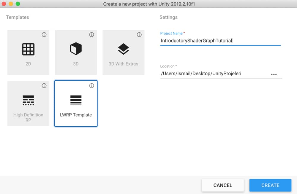
Let’s set up our project for Shader Graph. In this tutorial, I will use Unity3D version 2019.2.1. If you are using a different version, you may see some small differences but the general process should be the same.
Open Unity Hub and in order to create a new project click New.
From the Templates, select LWRP(URP) Template, and give a suitable name to your project. Then click Create. Wait until your project is created. This may take a few minutes.
When your project loaded, you will see a pre-established scene. We will not use it. You can delete the scene and all the files that come for that scene. Then create a new scene for your project.
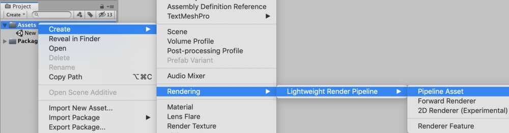
First of all, we have to create a pipeline asset. As you may guess, since we use LWRP, we need to create a Lightweight Render Pipeline Asset. To do this, right-click on the assets folder. Then follow the path Create-Rendering-Lightweight Render Pipeline and select Pipeline Asset.
We will see lots of graphics options in the created pipeline asset. When you select this asset, you will see the following in the inspector.
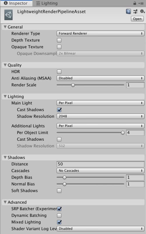
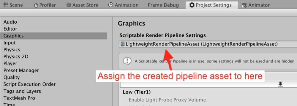
For now, we will not play with it but we have to tell the Unity that we will use these options. To do this, go to Graphics Tab in the Project Settings and assign the created pipeline asset to the slot at the top.
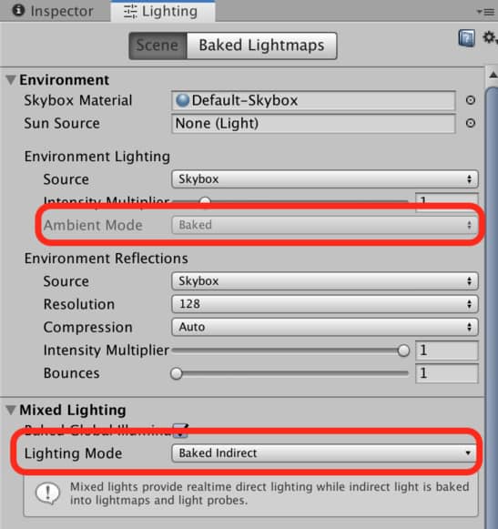
As we mentioned, currently, URP(LWRP) does not support some features. Therefore, we have to make some changes in Lighting options. We need to set the Ambient Mode to Baked and Lighting Mode in Mixed Lighting section to Baked Indirect as seen in the image below.
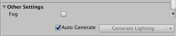
I also suggest you to tick the Auto Generate option in the bottom of the Lighting Tab.
Now, our project is ready to use Shader Graph.
PBR Shader vs Unlit Shader
When it comes to creating a new shader, you have two options: PBR Shader or Unlit Shader. Let’s see, what are they and when do we use them?
An Unlit Shader is a shader that no lighting model is implemented. Therefore, if you create an unlit shader and use it with a material, you cannot see any shading on the material since that matter cannot interact with light. An unlit shader is used when there is no need for lighting or when you want to implement your own custom lighting model.
A PBR Shader is a shader that a physically based lighting model is implemented. Therefore, you will not need to deal with lighting models and your image will be shaded without much effort. A drawback of this model is that you are restricted to work with the pre-implemented lighting model. On the other hand, this lighting model is sufficient for most of the projects. Probably you will not worry about it much.
For better understanding, look the image below.
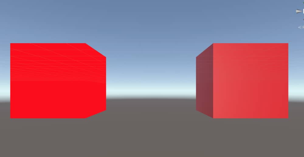
In this image, there are two cubes of the same size. The left one uses a material that an Unlit Shader attached. As you can see, there is no shading on the cube and even if it has a 3D geometry you can not distinguish the faces. On the other hand, the cube on the right uses a material that is attached to a PBR shader. As seen, it is clearly seen that illusion of 3D rendering obtained.
In the example below, we will create a PBR shader since it is sufficient for the results that we want to achieve.
Creating a shader with Shader Graph
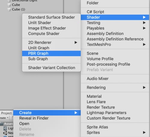
To create a Shader Graph, right click on the Assets folder, then follow the path Create-Shader. You can select either PBR Shader Graph or Unlit Shader Graph at that menu.
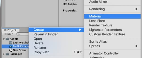
After you create a shader graph, you should change its name with a suitable one. In order to use this shader, you have to attach it to a material. The easiest way to create a material for a shader is by right-click on the shader and then choose Material in the Create menu. This will create a material for the shader that you have right-clicked.
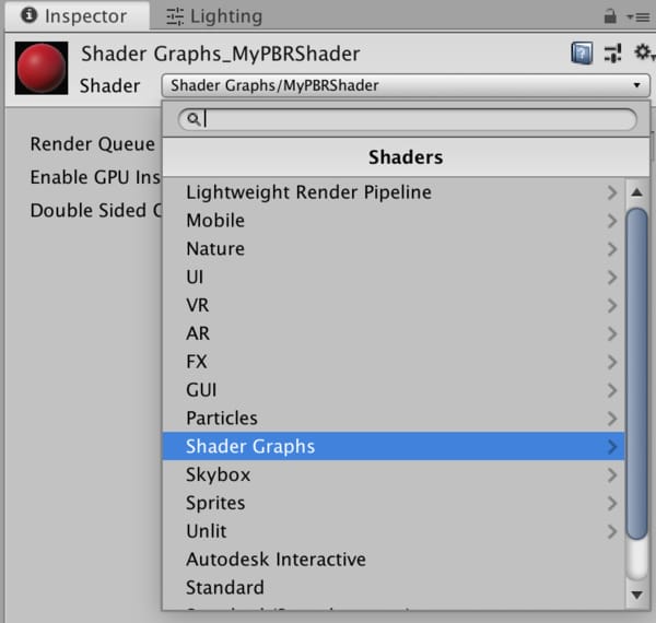
If you prefer to choose creating a material and then select the shader, you can also do that in the material inspector. Shaders that are created using Shader Graph are located under the Shader Graphs section in the drop down menu in material inspector.
Shader graph editor
After you create the shader, you can double click to open it. The shader graph will open in a new tab that is used to edit shader graphs. It is seen like this:
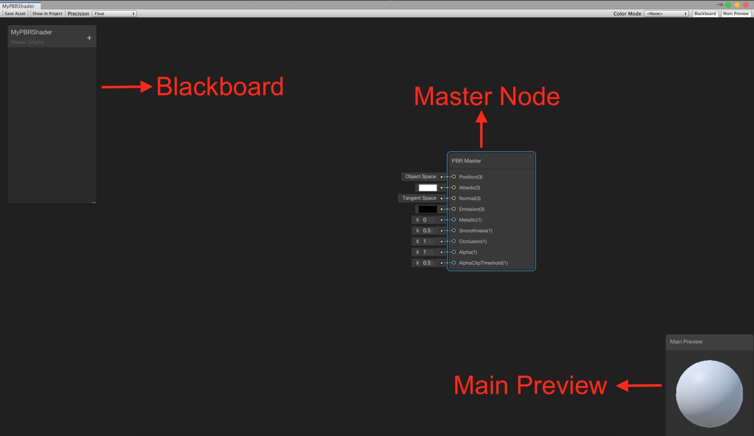
In the middle of the window, you see the Master Node. Since this is PBR Shader, you see a PBR Master Node. If we created an Unlit Shader, it would be an Unlit Master Node. The master node is the final destination for all the shader branches and all the nodes have to be connected to this node.
On the left, you see a small window. This is called Blackboard. We add the properties, that we want to access from the outside of the shader, using the + icon on the upper right corner of the Blackboard. For instance, if we want to add a Texture to this shader from the inspector in Unity Editor, we have to add a property. Added properties are listed on the Blackboard.
The small window on the bottom right corner of the Shader Graph editor is the Main Preview. You see the final result of your shader in the Main Preview.
If you do not want to see Main Preview or Blackboard, you can disable them from the buttons on the top right corner of the Shader Graph Editor.
When you finish your shader, you have to save it. The changes will not be seen in Unity unless the shader graph is saved. In order to save the shader, use the Save button at the top left corner of the Shader Graph Editor.
Adding nodes
Shader graph is a node-based environment. That means that we have pre-created nodes and by connecting them, we build new shaders.
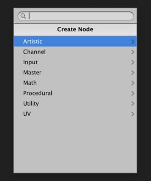
In order to add a new node, right-click while the mouse pointer over the editor, and select Create Node. A new menu will be opened and you can find the node that you want to add by navigating on the menu. Alternatively, you can search for nodes by writing their names.
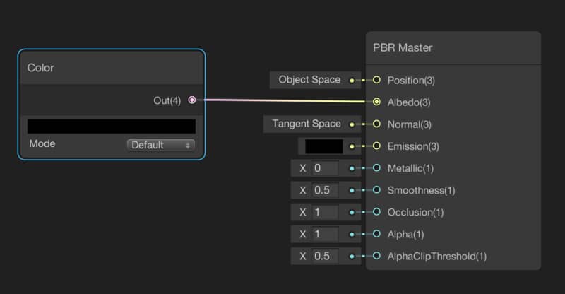
For instance, in order to add a Color Node, right-click and then follow the path Input-Basic-Color or just type Color when the menu is opened.
After you add a node to Shader Graph Editor, you can connect the node with other nodes. For example, you see the connection between a color node and the PBR master node in the image below.
As mentioned before, you can also create special nodes that can be accessible from the outside of the shader. These nodes are called Properties. To add a property, click the plus icon on the top right corner of Blackboard and select the type of property that you want to add.
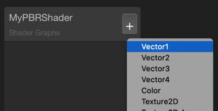
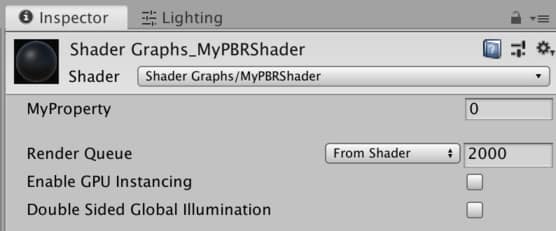
After adding a property, you can change its visible name which will be seen in the material inspector and its reference name that is used to access from a C# script. Reference names of properties start with an underscore as convention.
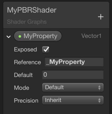
In order to use properties in a Shader Graph, you have to drag the property and drop it to the editor. You can see the property and change its value in the material inspector.
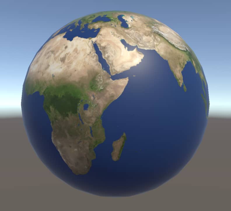
An example: the Earth Shader
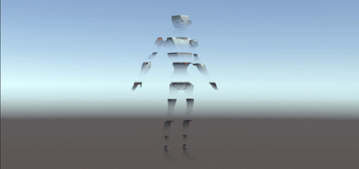
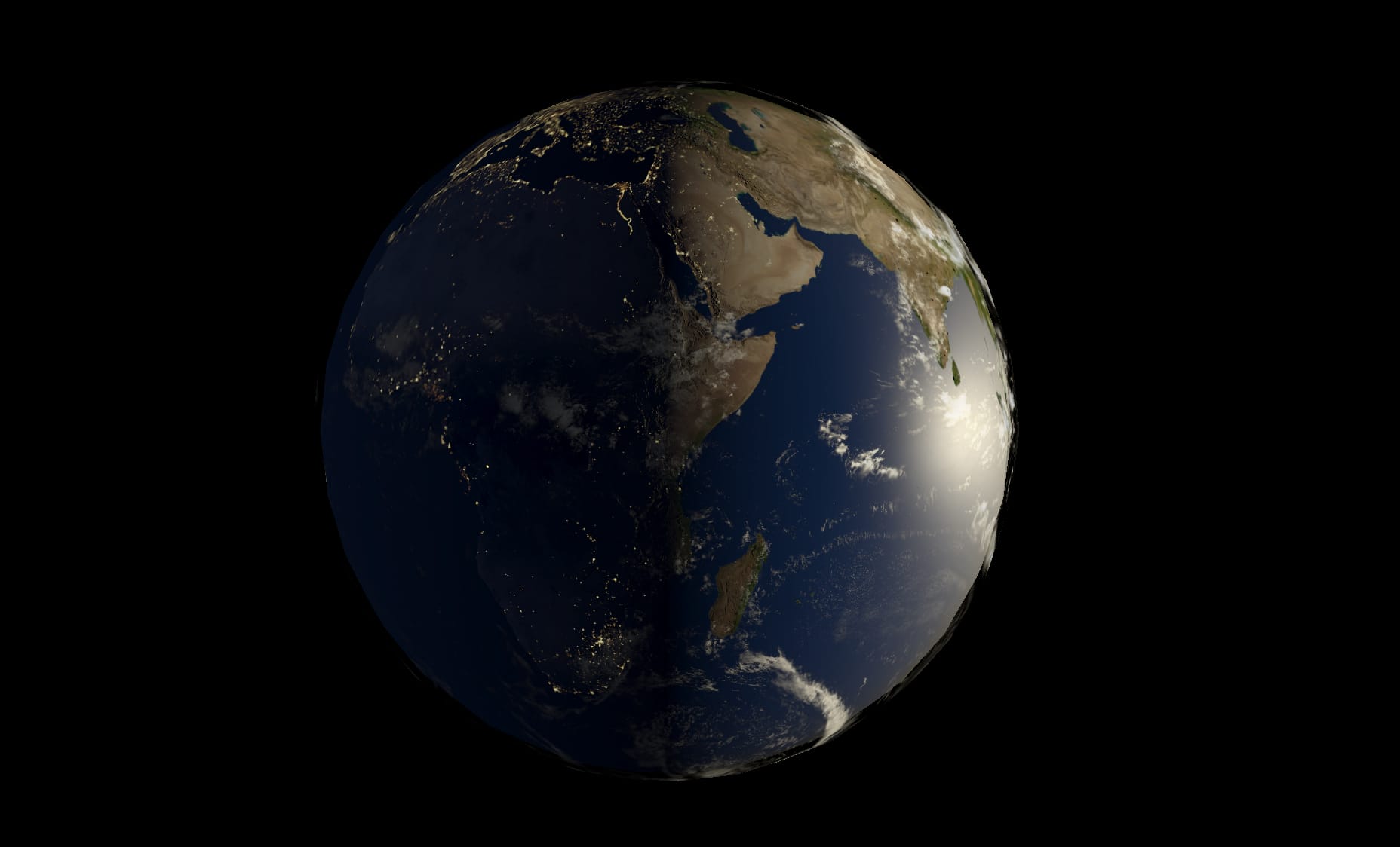
Now, let’s create a real shader. This will be an Earth Shader. I promise you that this tutorial is going to be very informative. At the end of this tutorial, you will be very comfortable while creating your own shaders. This is the final look that we will obtain at the end of the tutorial:
You can click here to download the textures that will be used in this project. You can also see the page, that I downloaded, from this link.
Create a new PBR shader with Shader Graph and change its name to EarthShader. Double click to open it.
Texture mapping
We want to obtain a sphere that looks like the Earth. Thus we have to cover the object with an Earth Texture. If we wanted to obtain a sphere that looks like a soccer ball, we would have to cover the sphere with a soccer ball texture.
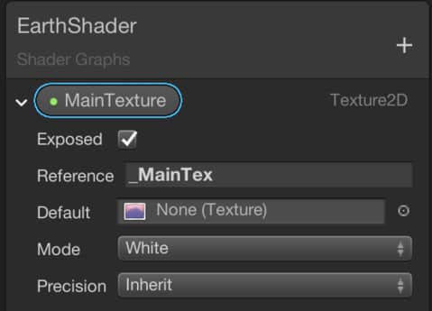
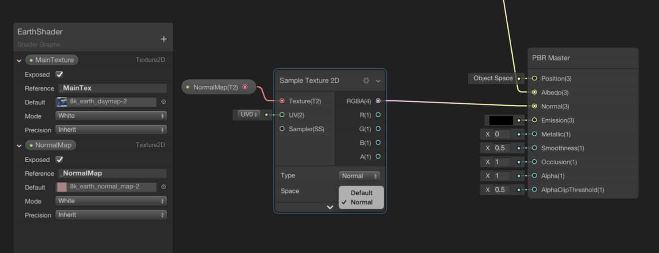
In order to add a Texture Property, click the plus icon on the top right corner of the Blackboard and choose Texture2D. Then change its name to MainTexture and its reference name to _MainTex.
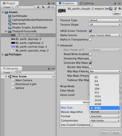
We can select a default texture that will be used in the editor. To add a default texture, click on the circle that is on the right of the Default slot. Then select the day map texture from the new window. I also suggest setting the maximum texture sizes to 8192 pixels for all the textures that are used in this tutorial. To do this, click on the textures in the Project tab and change their max size.
Drag the MainTexture property and drop it into the editor.
A texture is a 2D image. Our aim is to map this texture to the surface of the object. Thus, every fragment on the surface of the object will have a color value. This operation is called Texture Mapping or UV Mapping.
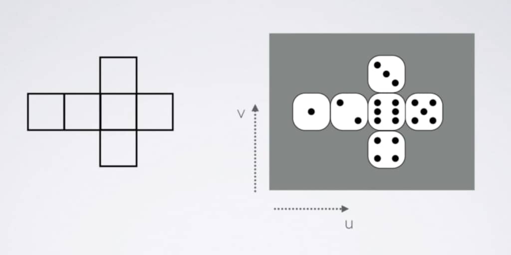
Above, you see the layout of a cube on the left and a dice texture on the right. The aim of the UV mapping is to match each point on the layout with the corresponding point on the texture image. Thus, every fragment on the surface of the cube gets a color value and when the cube is drawn on the screen, we see the cube as if it is a dice.
In order to map a texture onto a mesh, we use a Sample Texture2D Node in Shader Graph. We will connect the MainTexture property to the Texture port of the Sample Texture2D Node. Like any other node, Sample Texture2D Node also takes parameters and returns values. We will obtain color values for each individual fragment from the outputs of the Sample Texture2D Node. In computer graphics, colors are represented as 4-dimensional vectors. Each component keeps value for red, green, blue and alpha channels. The combination of these components gives us a final color. At the outputs of this node, we can get individual components of color values or directly 4-dimensional vector.
Let’s get back to our topic. Add a Sample Texture2D Node and make the connections as in the image below.
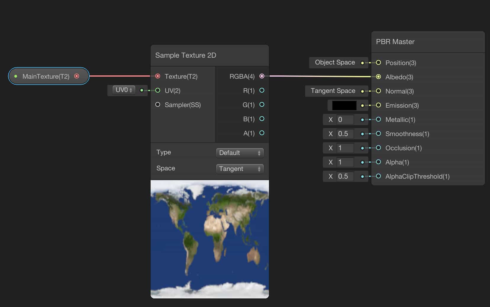
Numbers in parentheses at the ports of the nodes indicate the dimension of the value. For instance, the RGBA port of the node is a 4-dimensional vector. Likewise, B port is 1-dimensional. As you probably noticed, the Albedo port of the PBR master Node takes a 3-dimensional vector which means that if you connect a 4-dimensional vector, the only the first three components will be used and the last one will be discarded.
In Unity, Albedo is a term that is defined as the base color of a surface. In other words, each fragment on the surface of the mesh that uses this shader in its material gets the connected color value, that is connected to the Albedo port, as the base color.
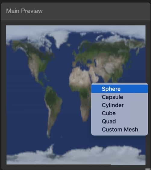
As soon as you connect the output of the Sample Texture2D Node to the Albedo port of the PBR Master Node, you should be able to see the result in the Main Preview. If you do not see a sphere in the Main Preview, you can switch the mesh with a sphere. To do this, just right-click on the Main Preview window and select Sphere.
Let’s turn back to the Unity Editor and check the results.
Create a material for this shader and add a sphere into your scene. Then assign the material to the sphere. You should be able to see the following:
Currently, it seems as if it is a model of the Earth that is printed on a glossy paper. But we will make it better step by step.
Normal mapping
Normal mapping is a method that is developed to increase photorealism and optimization. A perfectly smooth surface does not exist in real life. Every surface has a roughness more or less. Without a roughness, we cannot achieve realistic looking for most of the objects. On the other hand, if we try to create a roughness on the surface of a mesh, we increase the number of vertices. Obviously, this is not a good idea since it causes big performance problems.
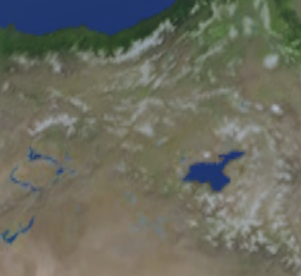
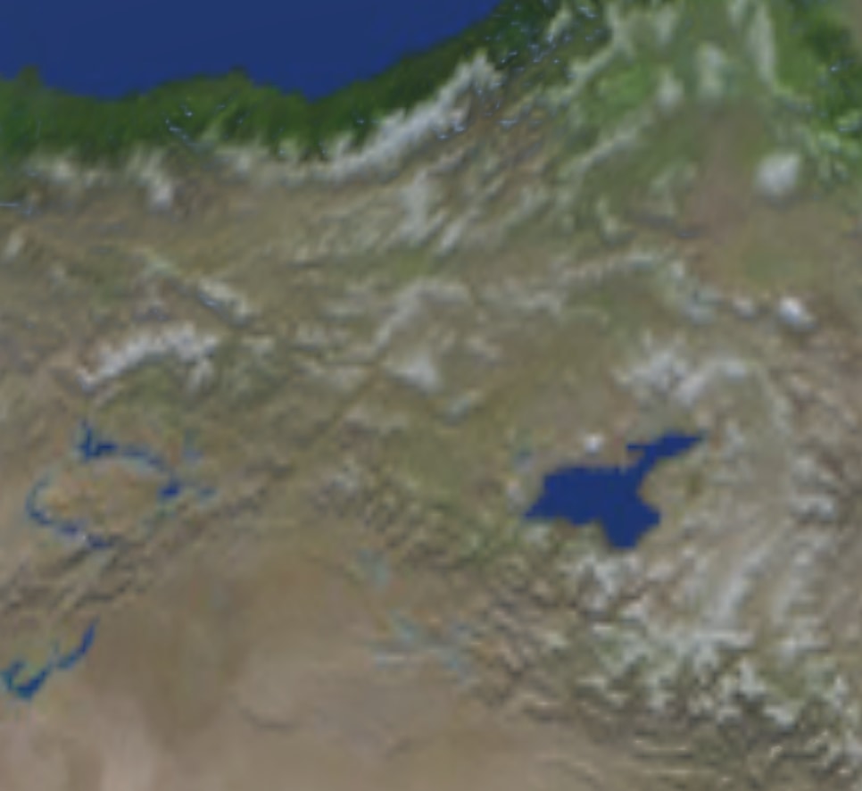
To overcome this problem, we use normal maps. For instance, a little later, we will add a normal map to our Earth Shader and if you look closer, you may see details as the images below. The normal map makes mountains visible.
Like texture mapping, normal maps are also 2-dimensional images that are mapped on surfaces of meshes. But this time, color values on them are not used for coloring a pixel but instead, used to manipulate the reflection direction of light. In normal maps, RGB colors represent a direction vector on the surface of the mesh, and thus, reflected light from each fragment behaves as if it is reflected from a small mirror that has a different orientation than the others.
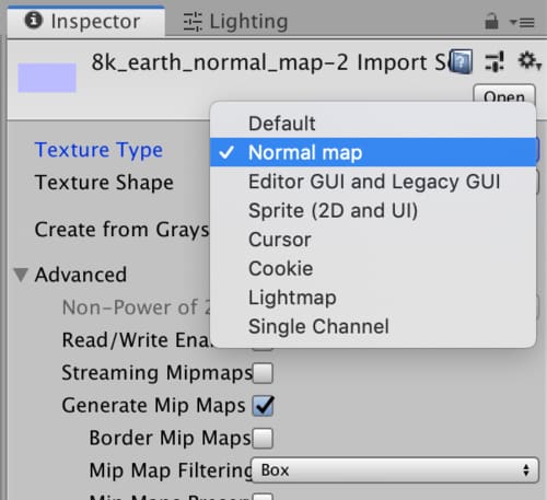
In order to use a 2-dimensional image as a normal map, we have to tell the Unity3D that we will use it as a normal map. To do this, click on the normal map texture that we will use in the Project Tab and check if the Texture Type is set as Normal map in the Inspector.
Let’s add a normal map to our shader. The procedure is the same as adding a texture map. We need to create a Texture2D property in the Blackboard and add a Sample Texture2D node into the graph. You also have to select Normal in the dropdown menu at the Sample Texture2D node.
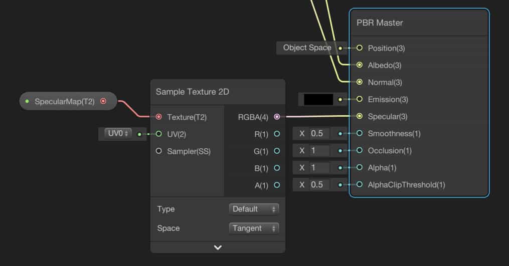
Adding a specular map

A smooth surface reflects light with little scatter. And this causes a shiny looking. To control this shininess we have two workflow options to choose from. The first one is the metallic setup and the second one is the specular setup. You can select the option that you want to use from the gear icon at the top right corner of the PBR Master Node.
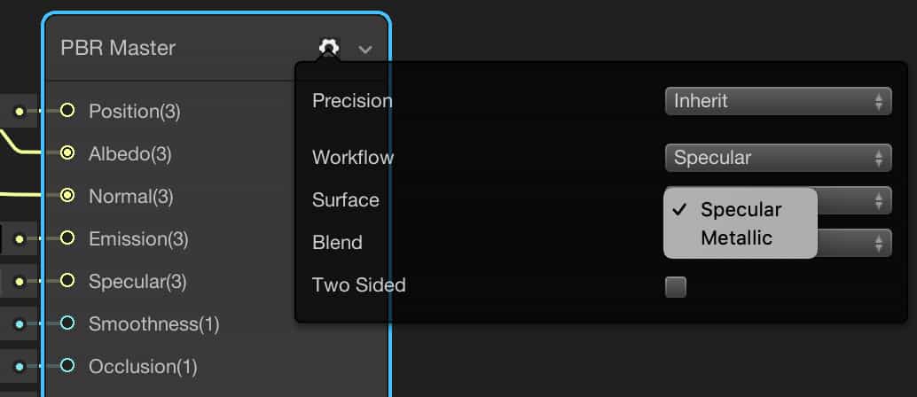
If you choose the metallic option, you can control how much the material close to a metal. Obviously, this is a way to determine the shininess of a surface.
The other option specular gives you the ability the control the color and strength of the specular reflection.
Whichever option you choose, you can achieve similar results. Since we have a specular map, we will use the specular setup in the Earth shader.
By adding a specular map, we determine the shiny and non-shiny surfaces on the earth. Since oceans and seas are much more reflective than the lands, in order to make it more photorealistic, they have to have different reflection properties.
As other maps, we need to create a Texture2D property and a Sample Texture2D Node.
I set the Source in Environment Lighting to Color and Ambient Color to Black. And also I set the Camera’s Background Color to Black. Then I see the following result.
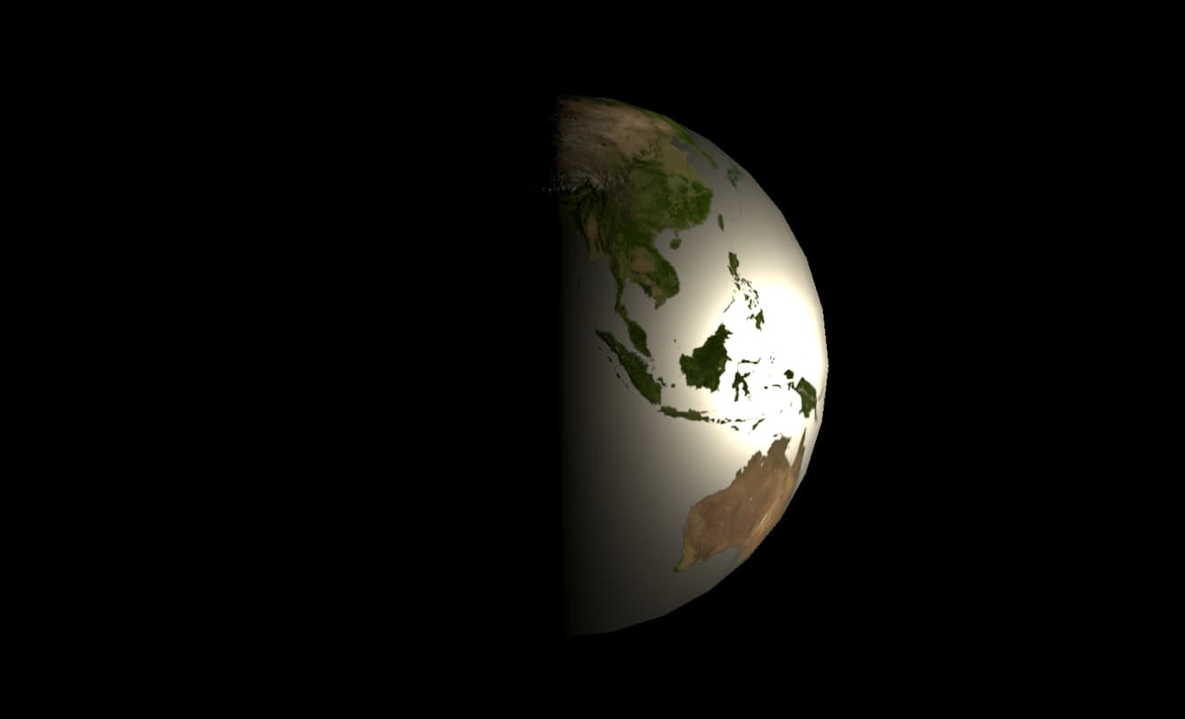
Oceans are looking like a mirror. This is not the result that we would like to achieve. A view dependent reflection is more suitable. To do this, let’s add a Fresnel Node and multiply it with the specular map before connecting to the PBR Master Node.
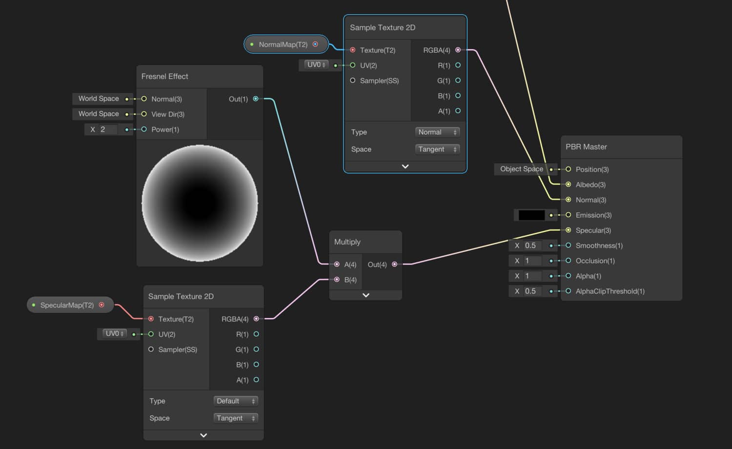
This is a better result:
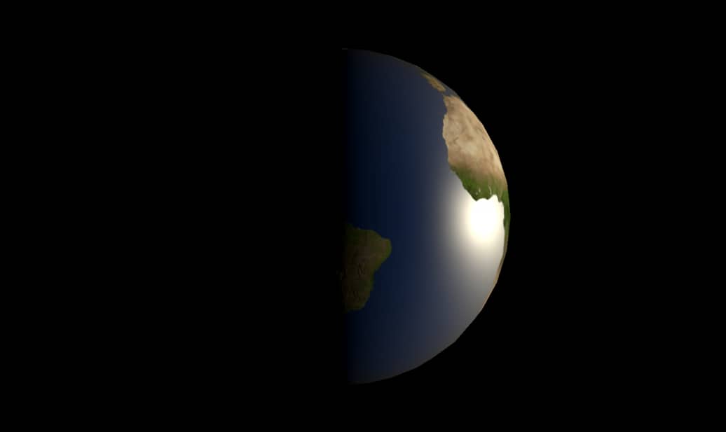
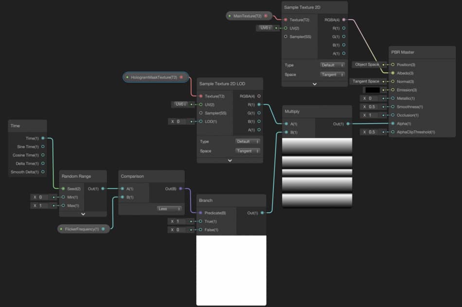
City lights
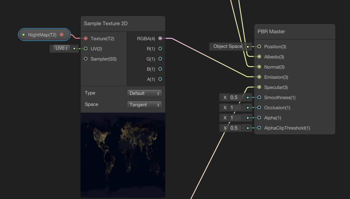
In order to simulate city lights, we will use night map texture in the assets folder and connect it to the Emission port of the PBR Master Node.
The dark side of the Earth seems nice. However, city lights should not be visible on the illuminated side as seen in the image below.
We can fix this problem using a dot product. If we calculate the dot product of the normal direction of the surface and the direction vector to the light source, we find if that fragment on the surface is looking to the sun or in the dark side.
If the dot product is greater than 0 this means that point is looking to the sun and smaller than 0 that point is looking to darkness. By remapping the result of the dot product we can achieve what we want.
Create a property to determine the direction vector to the sun. It should be in type Vector3. LightDirection is a good choice as a name for this property. Set its value to (1,0,0).
Then add a Normal Vector Node to your graph. Normal node gives you the Normal direction of a vertex. You should not be confused with the normal vectors of fragments that are modified by using the Normal map. Additionally, you can choose if this normal direction vector either in World Space, Object Space. or View Space. Since the Sun’s position is in World Space, we have to select World Space normals.
And finally, we should add a Dot Product Node and a Remap Node.
It should look like this:
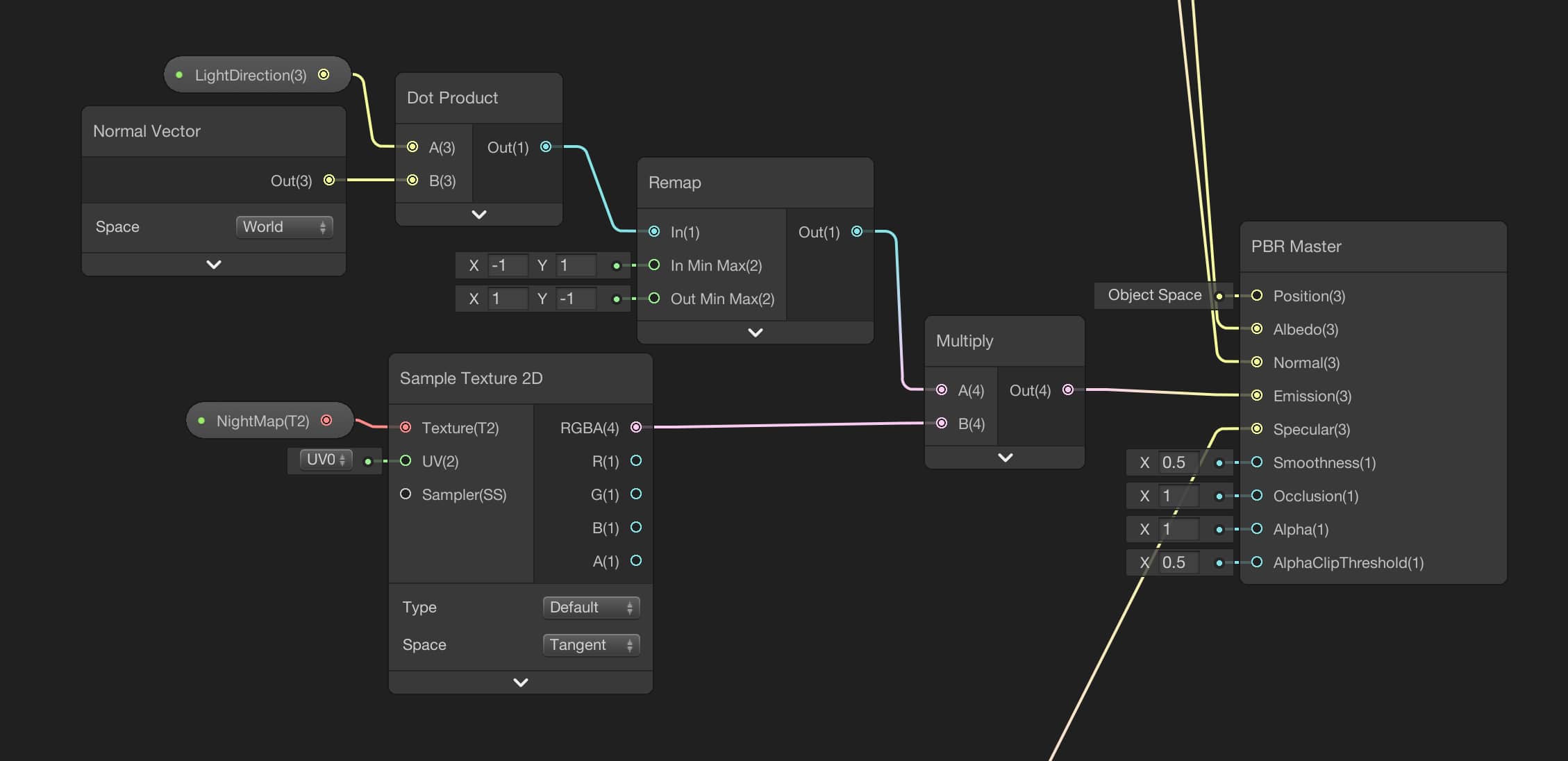
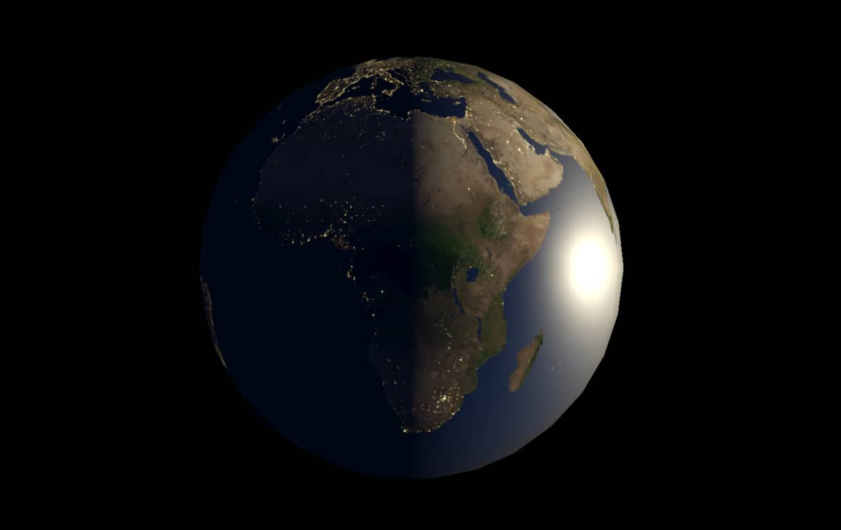
And this is the result:
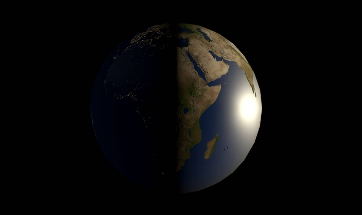
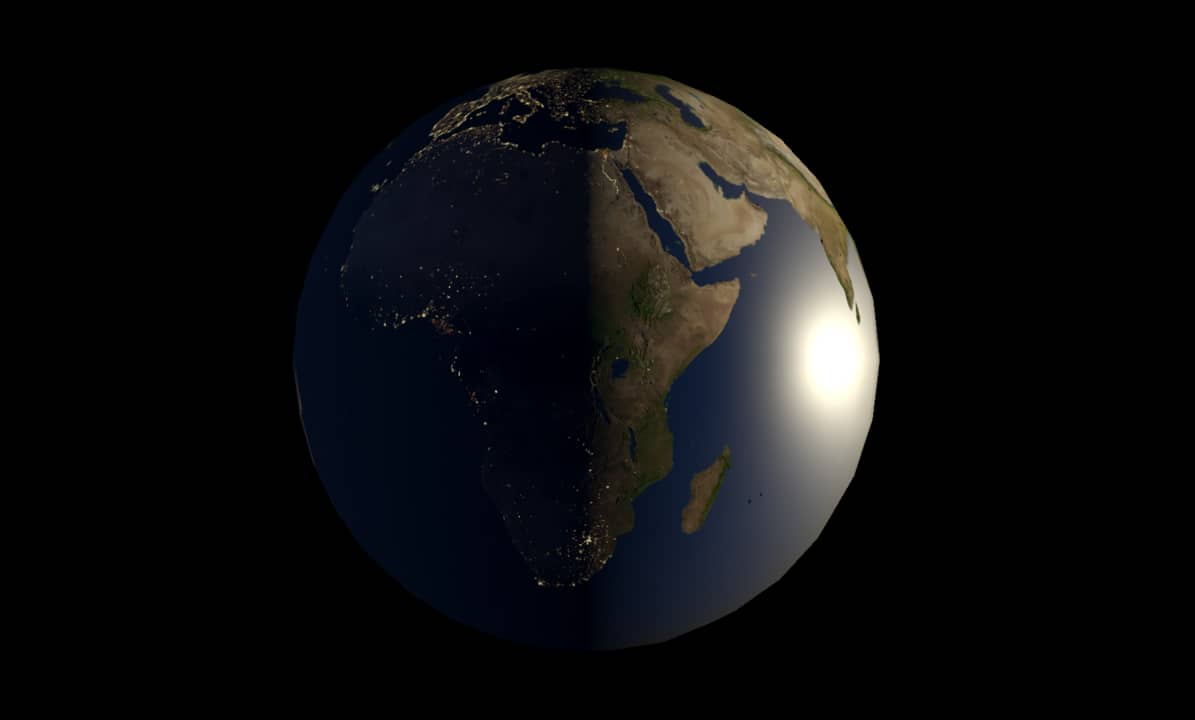
Almost done but it could have been better if the lights are brighter. An easy fix to this issue is just rearranging the Remap Node as the following:
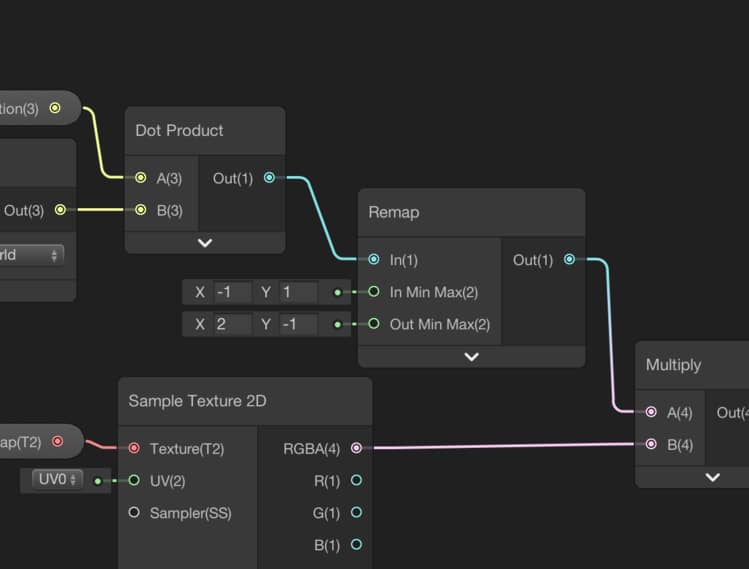
This not only makes the lights brighter but also makes lights visible at the twilight zone which is more realistic.
Clouds
Clouds are not on the surface of the Earth. They have some elevation. In default render pipeline of Unity3D, you can render more than one object from the same mesh in a shader code. This is called as Multi-Pass. On the other hand, multi-pass shaders are not supported in Universal Render Pipeline to make this pipeline more performance-friendly.
Our solution to this issue is creating a new sphere as the child object of the Earth. This new sphere will be the atmosphere of the Earth and it will be a little bigger than the Earth. We will map the cloud map onto the atmosphere and make the non-cloudy parts transparent. In order to do this, we will create a new shader also.
Let’s create a new PBR shader using Shader Graph. I changed its name to AtmosphereShader. Double click to open it.
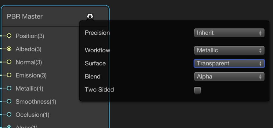
First of all, we should make the shader transparent. To make the shader transparent, click the gear icon on the top right corner of the PBR Master Node and set the Surface type to Transparent.
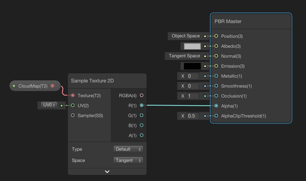
When you change the Alpha value, you should be able to see the change in the transparency of the model. By changing this value, you set this value for all the pixels. On the other hand, we can map a texture onto the sphere and determine the alpha value for every individual pixel.
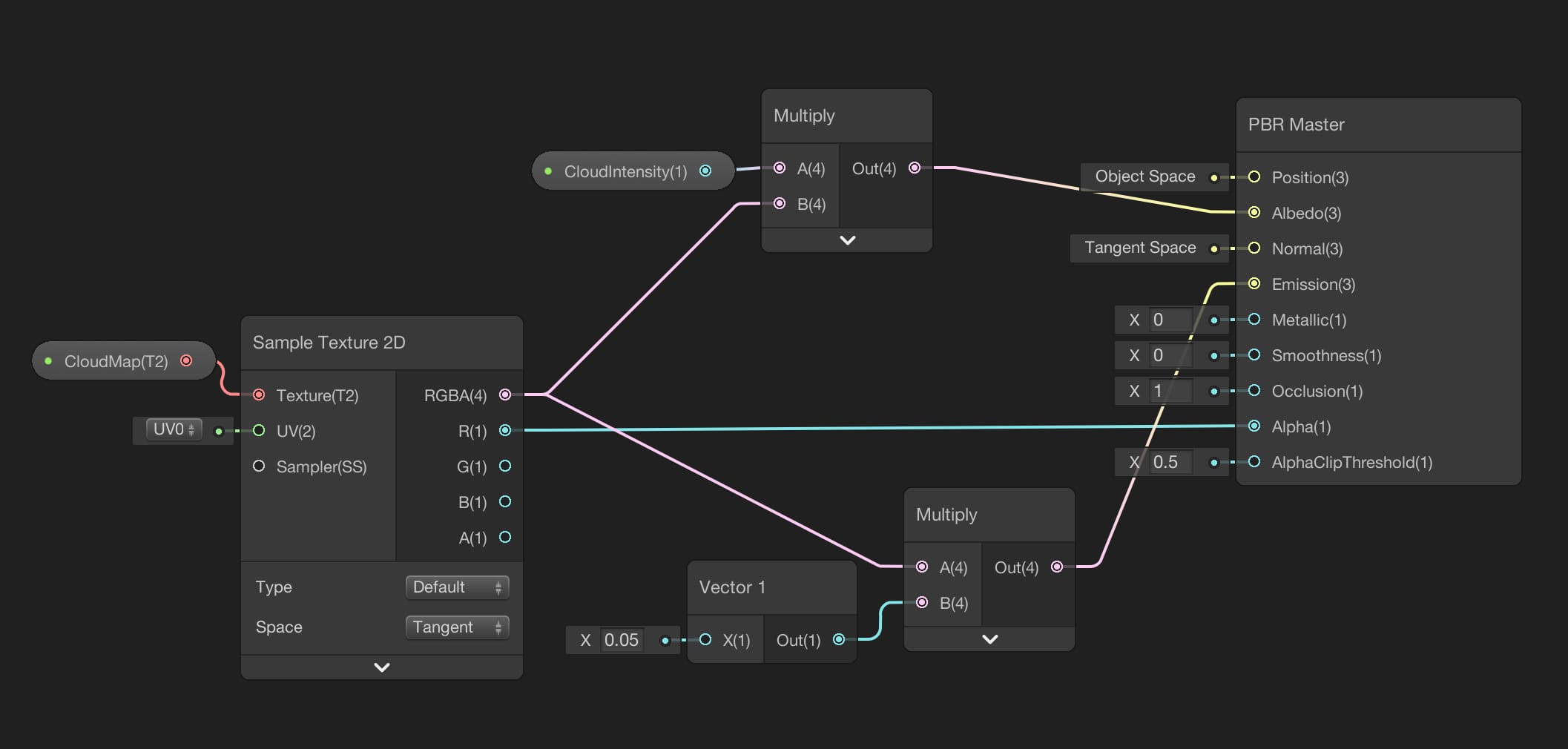
Create a new property for the Cloud Map and add to your graph a Sample Texture2D Node as usual. Then connect any of the R, G, B channel output to the Alpha port of the PBR Master Node. Thus, we have set which pixels will be transparent and which pixels will be opaque.
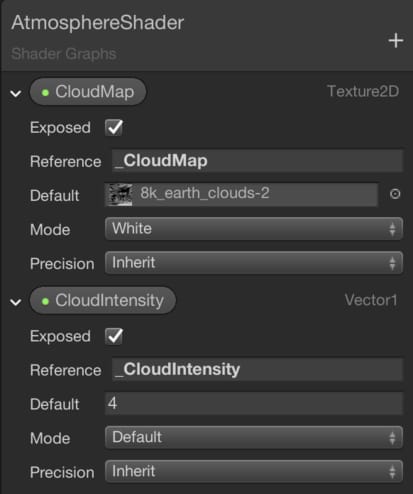
We can use the same texture as the Albedo. But it is a good idea to add a Vector1 value to arrange the cloud intensity. I also added a new Vector1 property to change the cloud intensity from the Unity Editor.
Then I multiplied this property with the RGBA port of the Sample Texture2D Node before connecting it to the Albedo.
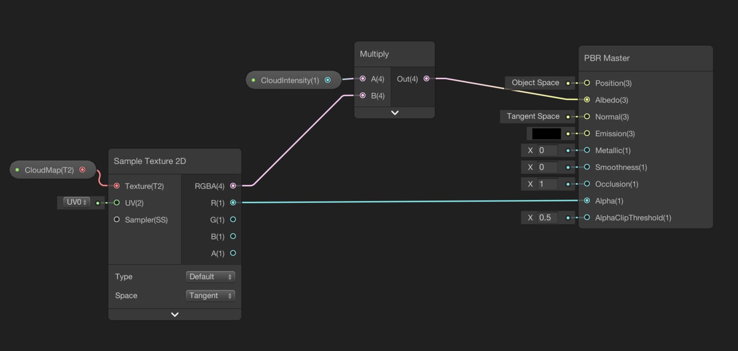
And I also want the clouds are visible a little when they are on the dark side. Therefore, let’s connect the RGBA port to the Emission port. But before doing this, again multiply it with a very small number, otherwise, they will be very bright and will look ugly. This is the final form of the Atmosphere Shader:
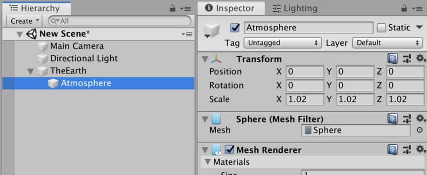
Create a new material for this shader. Then duplicate the Earth Model and scale it in all directions with 1.02. Thus, clouds will be a little higher. Then assign the material to the sphere that will be the atmosphere.
And you should see the following result. You should also be able to observe that while it is rotating city lights are dynamically changing:
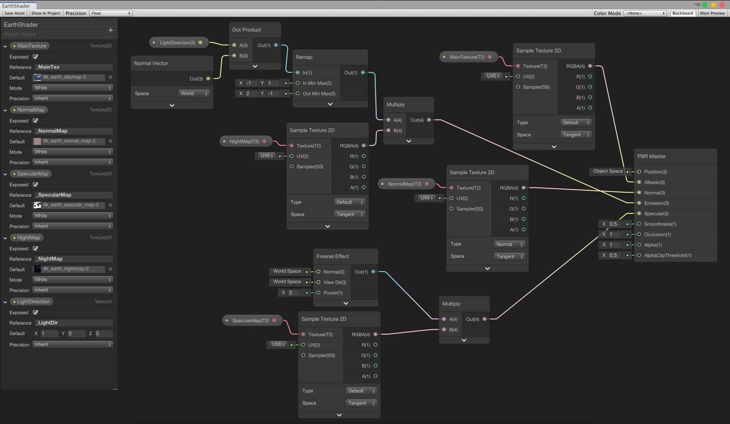
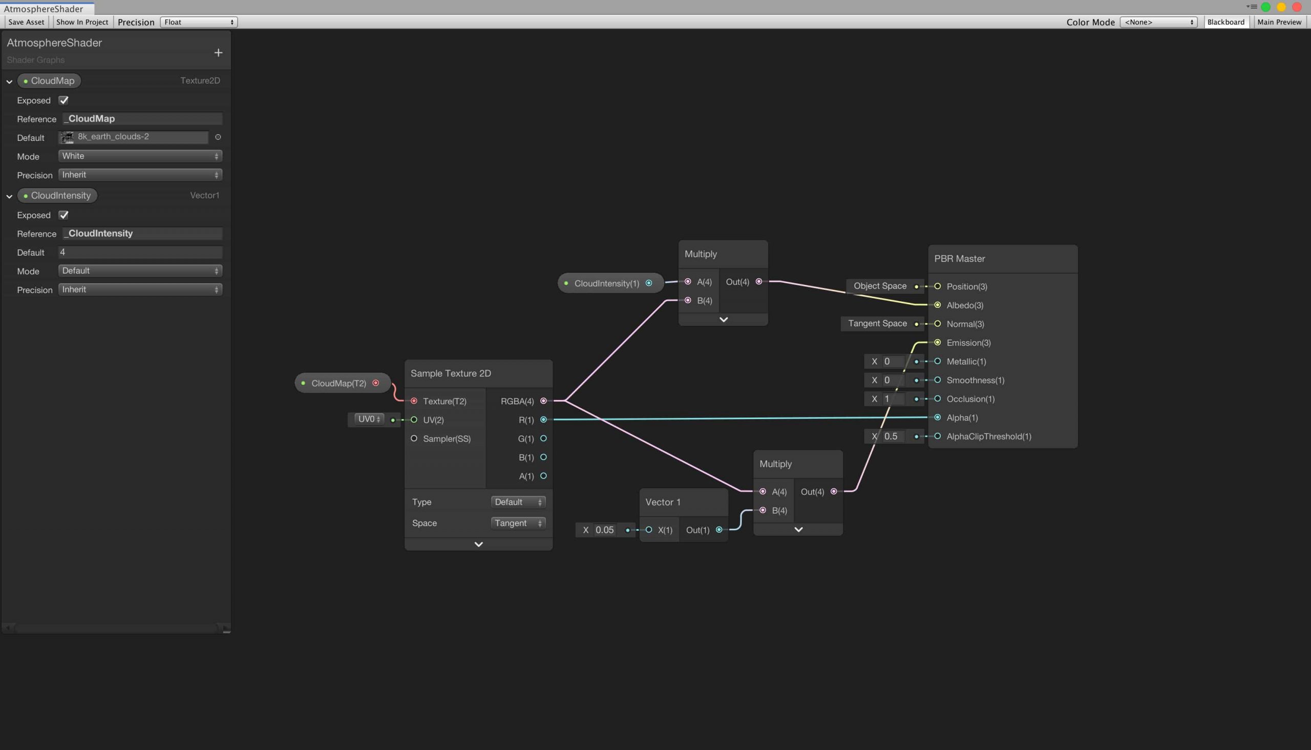
These are the full version of the shaders: