
Outline Effect using Shader Graph in Unity3D
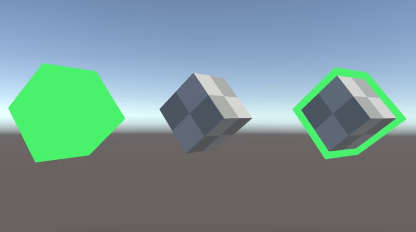
In this tutorial, we are going to create an outline effect for basic meshes using Shader Graph in Unity3D. We will encounter some restrictions of Shader Graph and learn how we can overcome this kind of restrictions. At the end of the tutorial, we are going to obtain the following effect:
Outline Effect
In order to create an outline for an object, we render an additional image with the same geometry and scale it a little bit to obtain the outline. Nevertheless, we also need to prevent to render the pixels of the newly created image when both images overlap. Therefore, we will see an outline effect around the object.
While we are writing our custom shaders using Cg/HLSL language, we have the opportunity to render more than one image of an object using the same shader. Each rendered image is created inside another Pass. However, multiple passes are not supported by the Shader Graph. Therefore we need a workaround to create an outline effect.
A solution can be the following: We may instantiate a new copy of the main object, scale it a little bit and assign a new outline material to this new object. This outline material will have an outline shader that makes the main object visible when two objects overlap over the Screen Space.
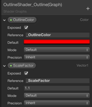
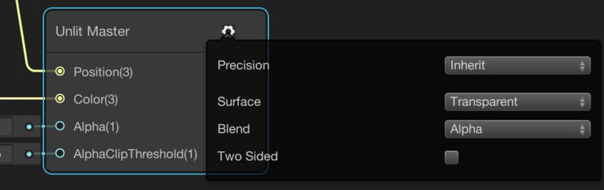
Let’s create an Unlit Shader Graph. Add two properties for OutlineColor and ScaleFactor. Since we want to access them from a C# script, it is a good idea to give them meaningful references.
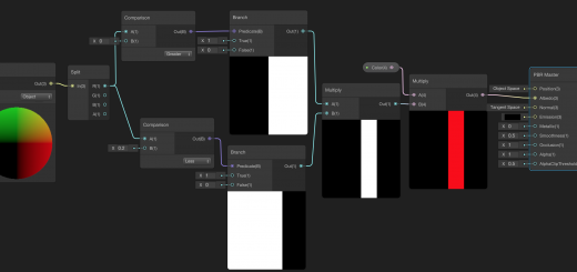
Our outline shader will be like the following:
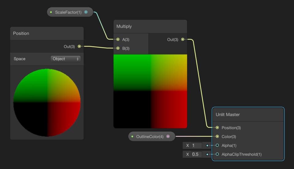
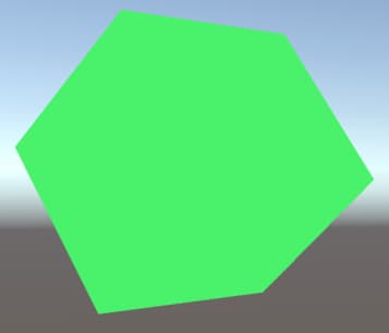
This is a very basic unlit shader that scales the object in its own space. This will create the following image. In the previous tutorial, we have seen how vertex manipulation works. This is also an example of that.
We are going to instantiate a copy of the object and assign this shader to the new object’s material. But since we do not want to render the fragments for overlapped pixels, we need to make some further arrangements. First of all, we need to change the Surface Type to Transparent for the Outline Shader.
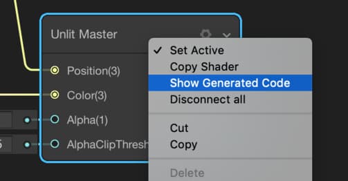
Second, right-click on the Master Node and select Show Generated Code.
Now, your favorite code editor will open, and you will see the shader code that lies behind the Shader Graph. This is a code which is written in Cg/HLSL and ShaderLab languages. These weird-looking languages may scare you but do not worry. We will modify only two rows. On the other hand, if you are more than a hobbyist you must learn shader languages in your future career. When you start to learn, you will see that there is no reason to be afraid.
Your generated code should look like this:
Shader "Unlit Master"
{
    Properties
    {
         ***
    }
    SubShader
    {
        Tags
        {
        ***
        }
        Pass
        {
            // Material options generated by graph

            Blend SrcAlpha OneMinusSrcAlpha, One OneMinusSrcAlpha

            Cull Back

            ZTest LEqual

            ZWrite Off

            HLSLPROGRAM

            ***
The first modification is changing the topmost row. Change it as follows:
Shader "Unlit/Outline"
Actually this is an optional change. The topmost row determines shader location in material editor’s shader selection menu.
The second modification is changing the Cull Back row. Here, let me explain what is culling.
Culling is an optimization method that allows us to determine which faces of a mesh will be rendered. For instance, we do not see the faces that do not look at us. Therefore, trying to make calculations are meaningless most of the time for the faces that we do not see. Therefore, it is a good idea to ignore them. This method is called culling. We have three options. We can choose Cull Back, Cull Front or Cull Off. When we select Cull Back, back faces will not be rendered. Likewise, Cull Front keywords make the front faces invisible. On the other hand, the Cull Off option renders both faces. Cull Back is the default option and if you do not change it, only front faces are rendered.
Let’s return our outline shader. When we duplicate the original object, the old object will be inside the new object, and hence, it will not be visible. It is not visible because outer object’s front faces are rendered and it veils the object which is inside. However, if we make the front faces invisible and backfaces visible of the outer object(outline object), we will see the original mesh. To do this, change Cull Back to Cull Front. Your new shader should look like this:
Shader "Unlit/Outline"
{
    Properties
    {
        _OutlineColor("OutlineColor", Color) = (1,0,0,0)
        _ScaleFactor("ScaleFactor ", Float) = 1.1

    }
    SubShader
    {
        Tags
        {
            "RenderPipeline"="LightweightPipeline"
            "RenderType"="Transparent"
            "Queue"="Transparent+0"
        }
        Pass
        {
            // Material options generated by graph

            Blend SrcAlpha OneMinusSrcAlpha, One OneMinusSrcAlpha

            Cull Front

            ZTest LEqual

            ZWrite Off

            HLSLPROGRAM
Saving the generated code does not work. So we have to copy the entire shader and paste it to another shader. To create a new shader(not shader graph), follow the same path with the shader graph selection menu but this time choose Unlit Shader instead of a shader graph. Then clear all the code inside and paste the copied code from the generated code.
Creating the Outline Object
Creating a copy of an object with the same position and rotation is very straightforward using a C# script in Unity3D. The following C# method duplicates the object, makes the new object a child of the original object, assigns a material and changes its properties. In addition, in order to prevent to render the shadow of the outline, we have to disable shadow casting. Finally, it returns the renderer component of the new object which we will use to enable or disable to make the outline visible or invisible.
Renderer CreateOutline(Material outlineMat, float scaleFactor, Color color){

    GameObject outlineObject = Instantiate(this.gameObject, transform.position, transform.rotation ,transform);
    Renderer rend = outlineObject.GetComponent<Renderer>();
    rend.material = outlineMat;
    rend.material.SetColor("_OutlineColor", color);
    rend.material.SetFloat("_ScaleFactor", scaleFactor);
    rend.shadowCastingMode = UnityEngine.Rendering.ShadowCastingMode.Off;
    outlineObject.GetComponent<OutlineScript>().enabled = false;
    outlineObject.GetComponent<Collider>().enabled = false;
    rend.enabled = false;

    return rend;
}
We will make the outline visible when the mouse is over the object and invisible when it exits. To do this we can use OnMouseEnter() and OnMouseExit() methods. Our final script will look like this:
using System.Collections;
using System.Collections.Generic;
using UnityEngine;

public class OutlineScript : MonoBehaviour
{
    [SerializeField] private Material outlineMaterial;
    [SerializeField] private float outlineScaleFactor;
    [SerializeField] private Color outlineColor;
    private Renderer outlineRenderer;

    void Start()
    {
        outlineRenderer = CreateOutline(outlineMaterial, outlineScaleFactor, outlineColor);
    }

    Renderer CreateOutline(Material outlineMat, float scaleFactor, Color color){

        GameObject outlineObject = Instantiate(this.gameObject, transform.position, transform.rotation ,transform);
        Renderer rend = outlineObject.GetComponent<Renderer>();
        rend.material = outlineMat;
        rend.material.SetColor("_OutlineColor", color);
        rend.material.SetFloat("_ScaleFactor", scaleFactor);
        rend.shadowCastingMode = UnityEngine.Rendering.ShadowCastingMode.Off;
        outlineObject.GetComponent<OutlineScript>().enabled = false;
        outlineObject.GetComponent<Collider>().enabled = false;
        rend.enabled = false;

        return rend;
    }

    private void OnMouseEnter()
    {
        outlineRenderer.enabled = true;
    }

    private void OnMouseOver()
    {
        transform.Rotate(Vector3.up, 1f, Space.World);
    }

    private void OnMouseExit()
    {
        outlineRenderer.enabled = false;
    }
}
Attach this script to the object that you would like to create an outline. Then create a material for the outline using the shader which we created above. And assign this material as the outlineMaterial in the C# script.
In this article, we have learned how we can create an outline effect. This tutorial shows some restrictions that we may face while developing our shaders using Shader Graph. We also see how we can overcome these restrictions. However, even though this shader works great for basic meshes, you may not see the same effect when you use it on complex meshes.
Thank you so much for this easy to follow tutorial!! Been looking for this exact pattern for a whole bunch of days, and you were able to explain it really clearly. Thanks again!!!
Just searched for 2 hours and finally debugged your script and searched why the values were not applyed
in stead of
rend.material.SetColor(“_OutlineColor”, color);
rend.material.SetFloat(“_ScaleFactor”, scaleFactor);
use the reference of your shader graph.
Example:
rend.material.SetFloat(“Vector1_4D184B9D”, scaleFactor);
rend.material.SetColor(“Color_34B06E5C”, color);
Hi Franck,
Thank you for your feedback. Even if you can use predefined references, I recommend to change them to meaningful strings. Generally, an underscore is added in front of the names of the properties for references as I showed in the article.
Dude this is something new! We have some sprites inside a spritesheet that need those outlines but the spritesheet we are using does not follow the regular convention of multiples of 4 neither have centered pivots.
Would you know if it works on this case?
Congratulations brother, this sure will be useful to tons of people having Outline problems using Shader Graph.
Unfortunately, this method does not work in that case.
Hi is there a way to make this outline work with complex objects?
Hi Haron,
There are a few approaches to this problem apart from the solution that is explained here.
Another way of creating an outline is to scale the vertices of the object along their normal vectors and using this new object as an outline as explained in the article. You should keep in mind that this only works if the object has no sharp points. For instance, this approach is not suitable for a cube since it has sharp edges and corners. On the other hand, it is suitable for a capsule.
Another approach is creating the outline in a 3D model creation software like Blender or Maya and assigning the outline shader to the outline object.
There is a fourth way also but I am not sure if it is possible with shader graph since I had not tried before. In this approach, the model is blurred using a blur shader and the actual image in screen space is subtracted. Therefore, we obtain an outline and we can render the outline as second pass. This is a more complex solution than the solutions that we have talked about before.
Hey great effect! I was wondering if this works on objects with the pivot not in centered. Most of my objects pivots are set to the bottom of the model and thus when the verts are scaled up the position of the outline doesn’t line up.
Hi Lawrence,
Unfortunately, this version does not work in your case.
I am not in a suitable condition to try it right now but there may be a way to do this. There is a Teleport Shader Tutorial which I wrote before, and there is a detailed explanation of how to construct a shader that manipulates vertices even if the model is built in a non-standard manner. It could not work directly for your shader but you may use it as a starting point. As I told, currently I cannot try it but it deserves trying.
You can see the Teleport Shader Tutorial by clicking Shader Graph Tutorials link on the left menu bar.
On the other hand, there is another method of creating an outline if your models do not have sharp points. In this method, you need to change the position of the vertices a little bit in their normal directions. There is also a node in the shader graph for getting vertex normals.
I hope this helps.
Try adding the normal vector (multiplied by an ‘outline size’ float) to the position. This way wherever there is a vertex it will be pushed out in the direction of the normal.
Thank you! This is perfect. I had some weird outline scripts and stuff, but this works so much better than any of those
You are welcome. I am very happy to see that it is helpful for you. On the other hand, keep in mind that this only works for basic meshes that do not have holes or concave parts.
Thank you for great tutorial.
If you want to use this shader for dynamic gameobjects that have rigidbody and collider attached.
For it to work properly you can destroy the instantiated outline objects rigidbody and collider.
Set variables:
private Component rigBod;
private Component theCollider;
Then copypaste following text to lower part of the code. Not inside the Start function.
theCollider = outlineObject.gameObject.GetComponent(typeof(Collider));
Destroy(theCollider);
rigBod = outlineObject.gameObject.GetComponent(typeof(Rigidbody));
Destroy(rigBod);
NOTE:
Batching Static seems to make the outline object to be the combined mesh.
Hey, thank you very much for your contribution. I hope this will also be useful to others.