
Creating a Teleport Shader using Shader Graph
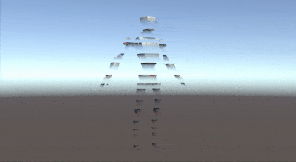
In this tutorial, we will create a Teleport Shader using Shader Graph in Unity3D. At the end of the tutorial, we will obtain the following effect.
This is a part of our tutorial series in Shader Graph. We have several Shader Graph Tutorials. In order to check them out, you can click here.
We will see how we can…
- transform position vectors between coordinate spaces.
- manipulate vertices.
- create transparency.
- generate the HLSL code behind the Shader Graph.
- solve the ZWrite problem.
Setup and First Steps
In this tutorial, I will use Robot Kyle as the model. You can download the model from the asset store. Nevertheless, it is not necessary and you can use any model you want.
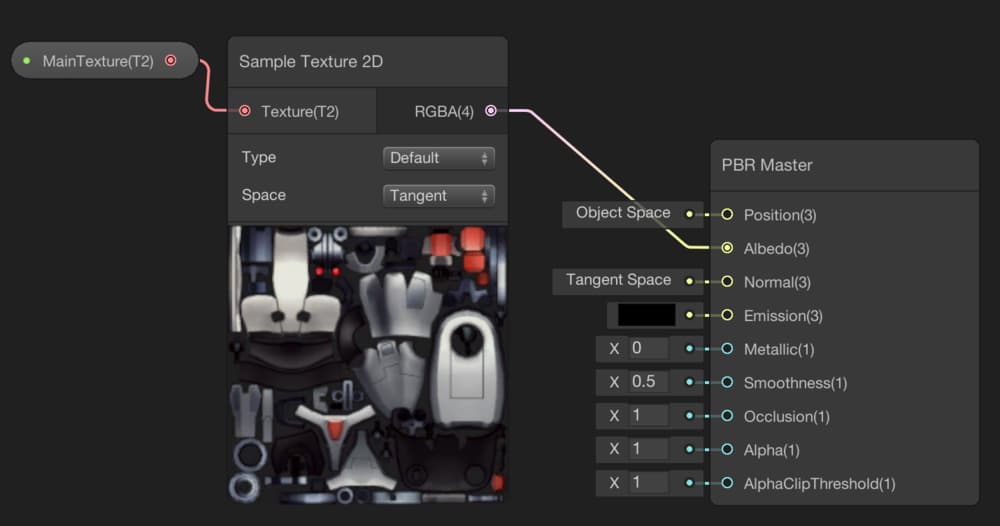
Create a new PBR Graph and call it TeleportShader. Add a MainTexture property for the texture of the model and add it to the shader graph. Then you need to create a new Sample Texture2D Node in order to map the texture to UV coordinates. Finally, connect it to the Albedo port of the PBR Master Node.
Up to now, there is no fancy stuff, but the next two parts will be more interesting.
Teleport Part
Our aim is to move vertices from the top of the object to the bottom. In other words, we will compare the y-component of a vertex position with a reference float number. If the y-component of the vertex position is greater than this reference, then we will move that vertex 50 units in the upward, i.e we will add a Vector3(0,50,0) to its actual position(50 is not an important number, you can change it as you want). If we decrease the reference number, then the object’s vertices will move to their new positions from the top to the bottom.
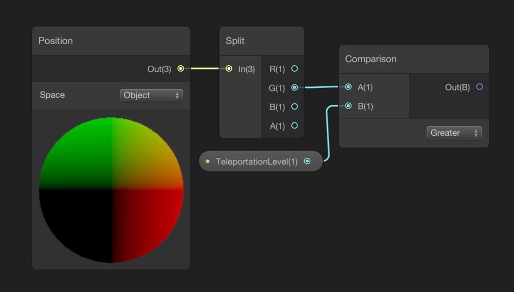
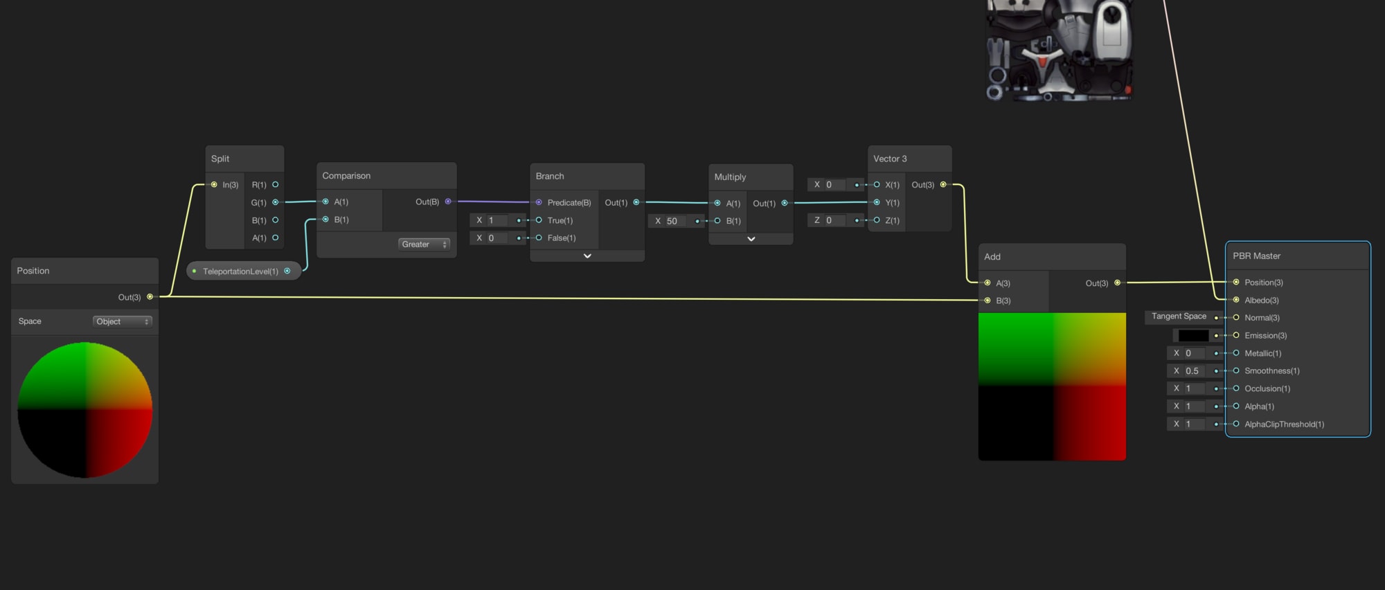
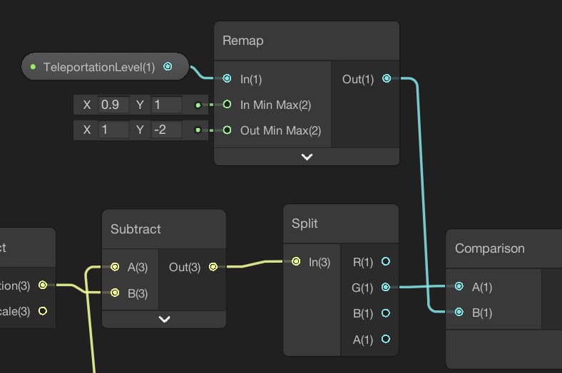
Let’s add a Position Node to get the position of the vertices and change its coordinate space to Object Space. Then split it using a Split Node, and with a Comparison Node, compare the y-component of the position with a reference number. For the reference number, you can create a new property. We will see later that TeleportationLevel is a good name for this property.
As I mentioned above, we will add 50 units to its y-component if it is greater than the TeleportationLevel. To convert the boolean value of the output of the Comparison Node, we need to use a Branch Node. Then add a Multiply Node, a Vector3 Node, and an Add Node. Arrange them as following:
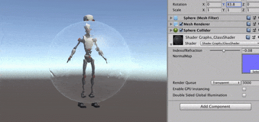
Save your shader, create a material for it and check what you get.
Oops! This is not the effect we would like to achieve. While our shader works as expected for the sphere, this not the case for Robot Kyle. The reason for this problem is object space coordinates do not correspond with our coordinate space. We told above that our shader works for the sphere as expected but actually this is also not true. If we rotate the sphere around x or z-axis, we will see that it is not working properly. Our shader should work in any mesh or any rotation without any special arrangement. To solve this problem, let’s do some math.
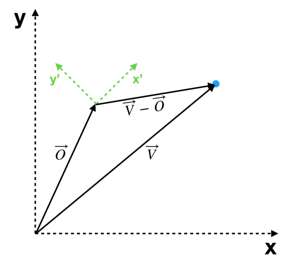
In the diagram above, there are two different coordinate spaces. Assume that the axis which is black represents the world space and which are orange represents object space. Actually, what we want to achieve is to check the vertex positions relative to object’s position and if it corresponds with our comparison, move it to another position.
In order to obtain the position of a vertex which is relative to position of the object, we can subtract world-space vertex position( \( \vec{V} \) ) from object’s position( \( \vec{O} \) ). You should be careful here. We make these calculations in world space. Therefore, we have to transform world space positions to object space before connect it to the PBR Master Node.
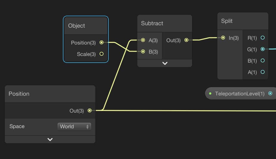
In Position Node change the coordinate space to World. Add an Object Node and subtract the position of the vertex from the position of the object as follows:
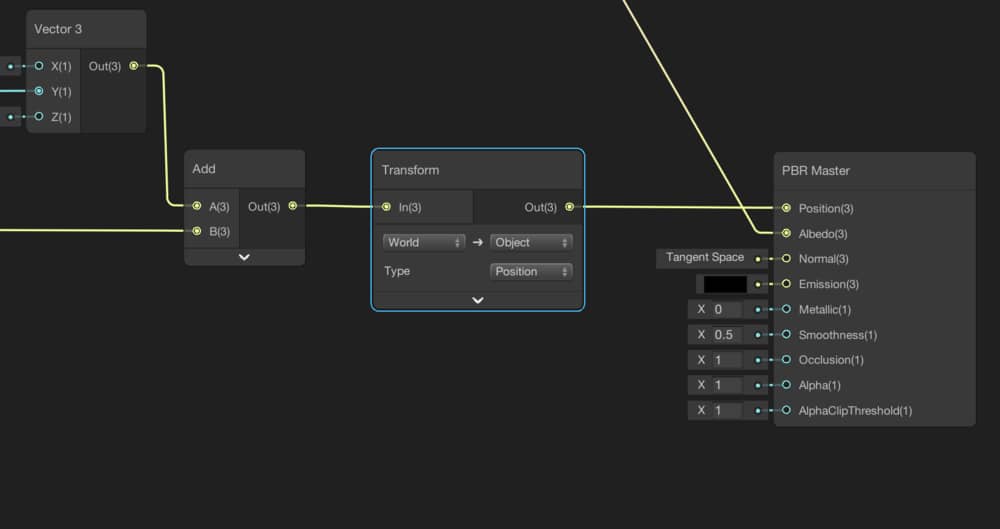
As I told you before, this calculation is in world space and before connecting this branch to PBR Master Node we have to transform it to object space. To do this, we use the Transform Node. Locate a Transform Node between Add Node and PBR Master Node.
And this is the result:
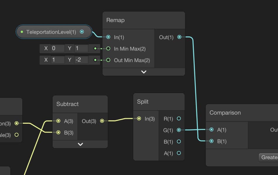
We will control TransportationLevel using a C# script and a programmer probably would like it to be intuitive for someone who will use this shader. Therefore, it is a good idea that restricting the value of TransportationLevel between 0 and 1. We can use a Remap Node to remap this value in a decreasing manner.
Hologram Part
We have already created a Hologram Shader before. You can click here to see that tutorial. Here, I will explain briefly how this works.
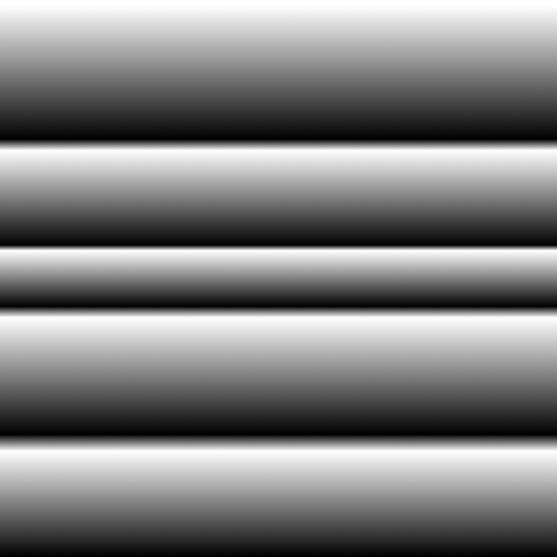
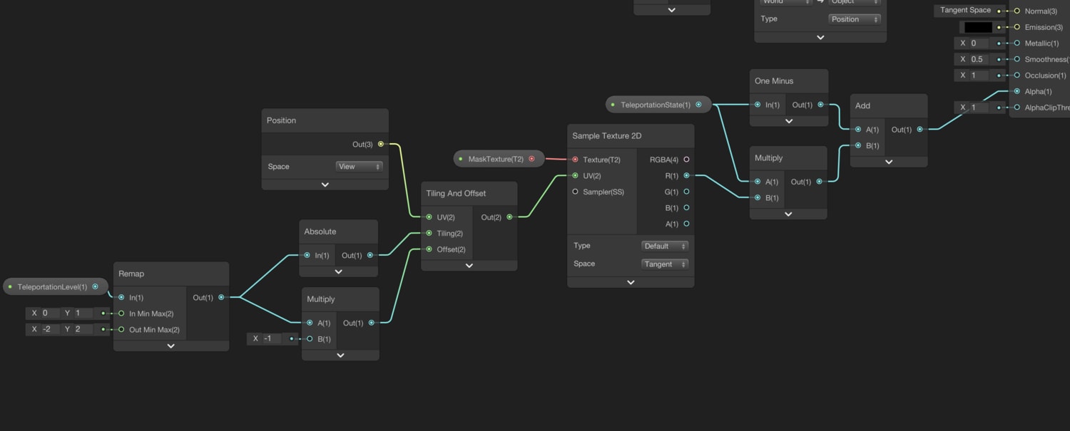
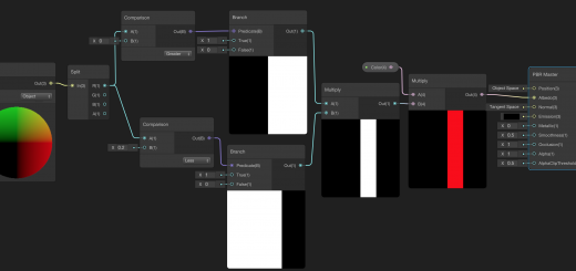
Our aim is to create a scrolling transparency by using a MaskTexture(you can use the texture on the right). To do this we need to change the surface type to Transparent from the gear icon on the PBR Master Node. While we change TransparencyLevel, tiling and offset values also change according to Transparency Level. We also need to prevent transparency when teleportation is not executed. To obtain this, we create a new float property for TeleportationState. We will set it either 0 or 1. Hence we will make Alpha value 1(fully opaque) when transportation is not running, and otherwise determined value within this branch. You can check the graph below.
And this is the result of this branch(without teleport part):
I want the following: During teleportation, the hologram part should start at the beginning but the teleport part should wait until 90% of the time. Then in a short period of time, teleportation should be run. To do this, change the minimum input value of the Remap Node in the teleport part to 0.9.
Full graph of the teleport shader is the following:
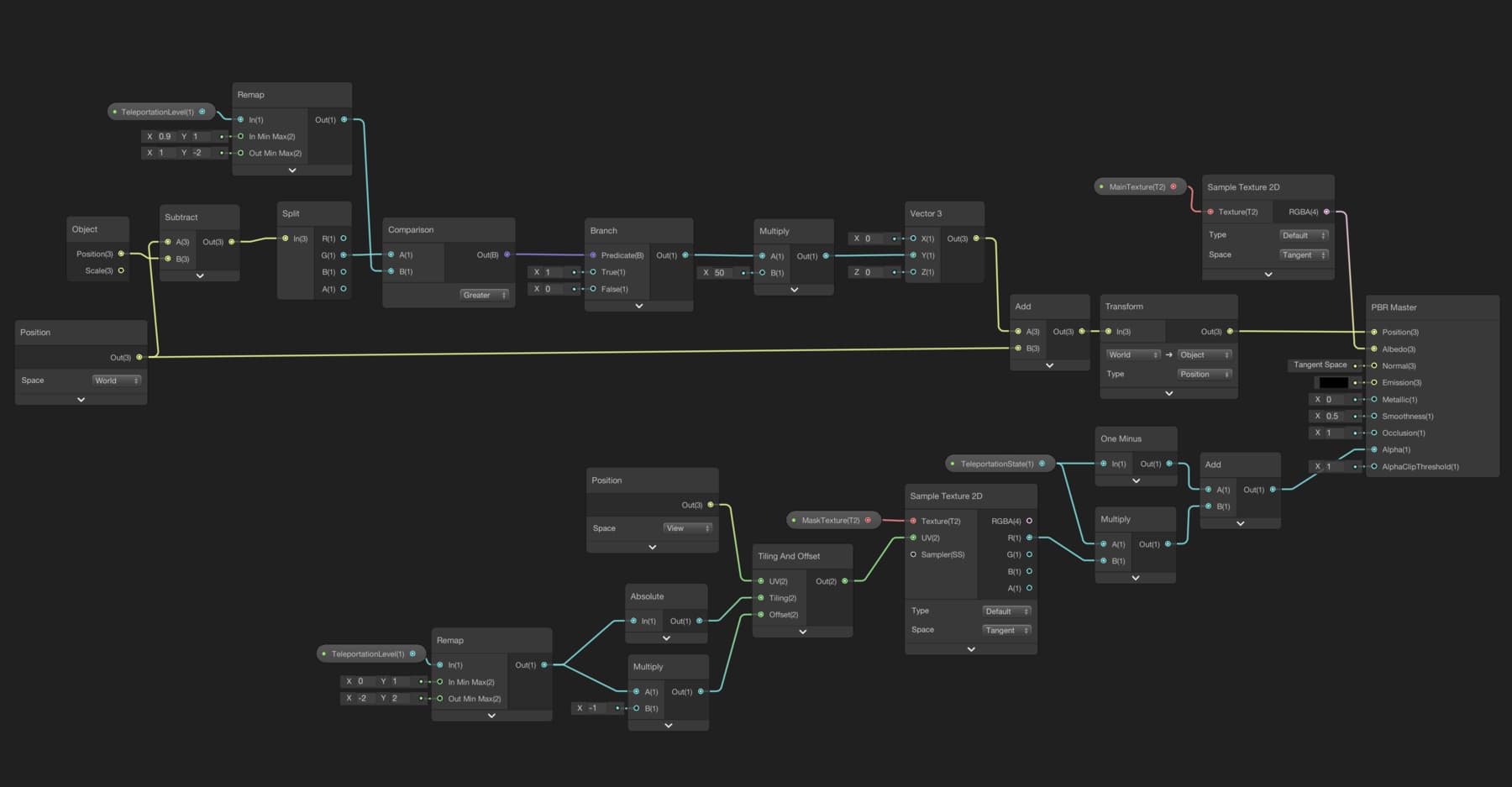
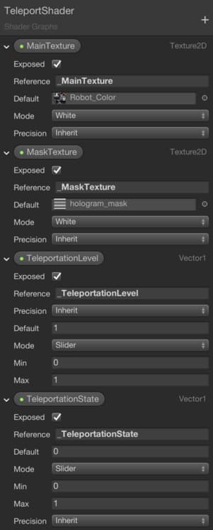
Also, these are the properties for the teleport shader:
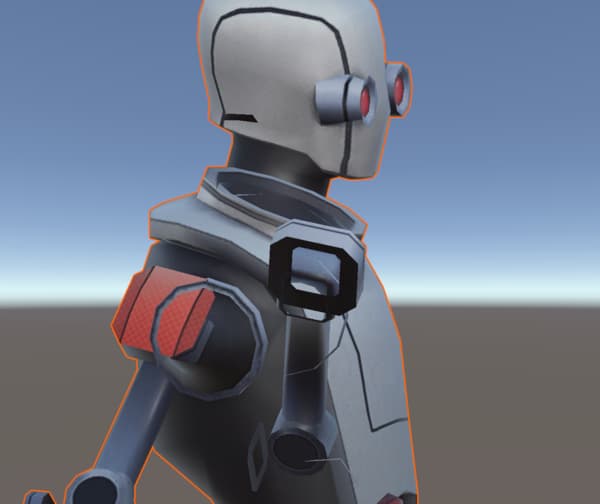
Let’s see what we get:
Solving ZWrite Problem
Normally, when objects are rendered by the GPU, fragments are rendered from the most distant to least distant. In other words, if there is more than one fragment that is located in the same pixel, then the closest fragment is rendered. This information is stored in Depth Buffer.
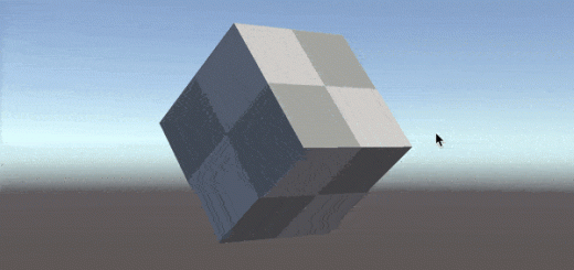
On the other hand, in the Shader Graph, if we set the Surface Type as Transparent, overwriting onto the existing fragments is switched off, and hence we see the following problem:
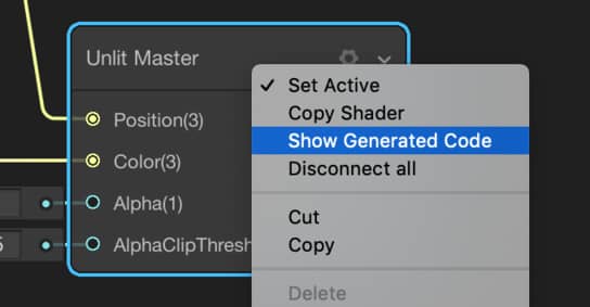
In the image above, we set the surface type to transparent. However since the Alpha value is 1, we expect an opaque looking. Nevertheless, it seems quite weird. There is a workaround for this problem. We will generate the Cg/HLSL code, make the necessary changes and use the new shader. To generate Cg/HLSL code, right-click on the master node, and select Show Generated Code.
We will change two rows. Changes are seen in the following image:
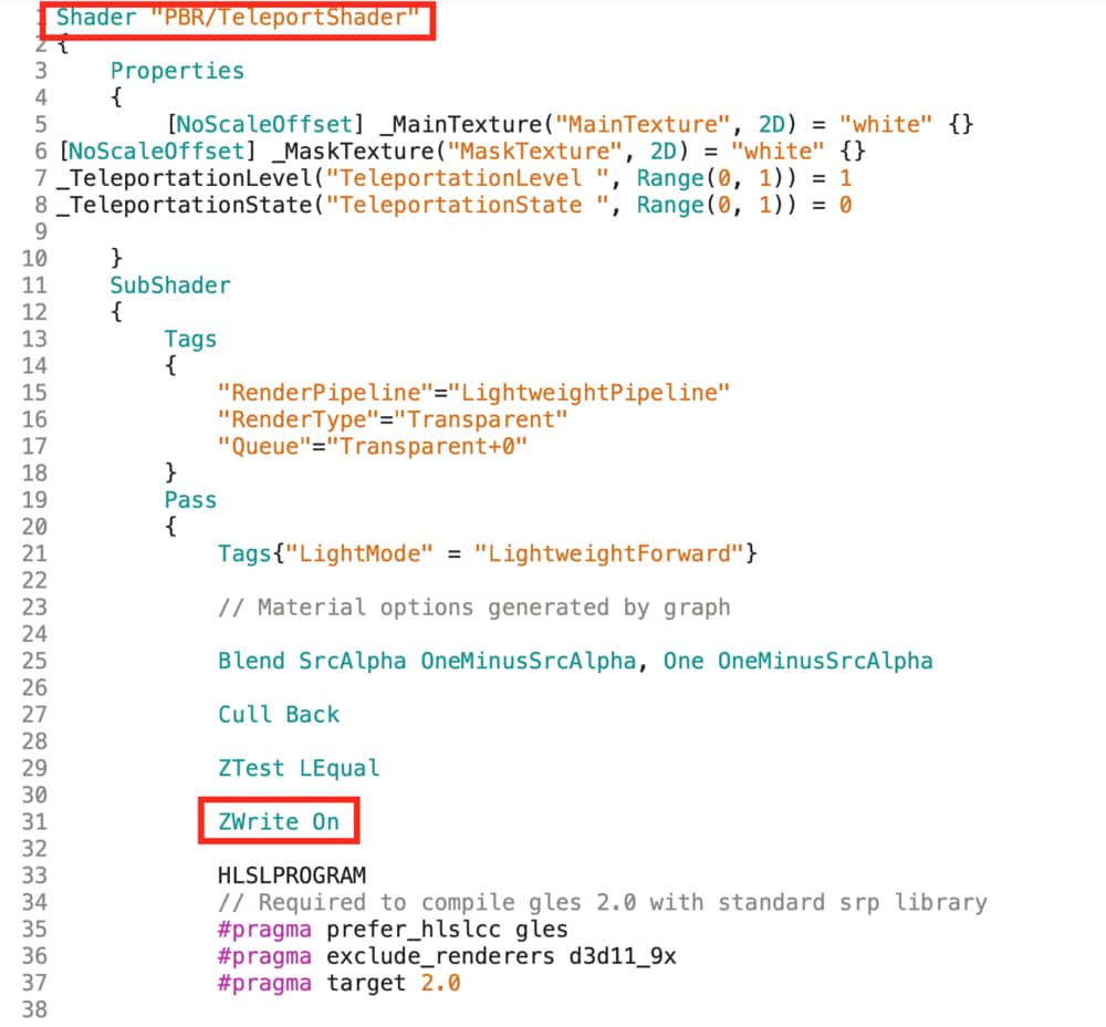
The topmost row is an optional change. It determines the path of the shader in the material inspector. The change which solves our problem is the second one: Switching on the ZWrite.
Copy all the teleport shader code, create a new shader(not shader graph) and paste the whole code. Finally, you need to choose this shader in the material inspector. This solves the problem.
Final teleport shader should look like this:
This is kind of shader graph tutorial I’ve been searching past 1 year. Love the way you explain the changes after adding node, and the way you explain the node and reason using it. Looking for more content and thanks for kindly sharing it !
Hi Richard,
Thank you very much for your nice comments. I am working on new tutorials about shader graph and shader development with Cg/HLSL. I hope new tutorials will be helpful also.
I have read several posts here about shader graph. I have a request, can you make the image more hi-res? Especially node group picture, the text is blurry because of the resolution is too low. Thanks in advance.
I think you are right. I will definitely do so. Thank you again.