
Glass Shader using Shader Graph in Unity3D
In this tutorial, we are going to create a glass shader using Shader Graph in Unity3D. This is a part of our tutorial series on Shader Graph and if you have not seen our tutorials yet, you can click here to check them out.
At the end of this tutorial, we will obtain the following shader.
In this tutorial, we will see…
- how you can use Render Texture to get the image of what camera sees
- creating the illusion of refraction to achieve better photorealism
- using a normal map to create a deformed or brushed glass.
Render Texture
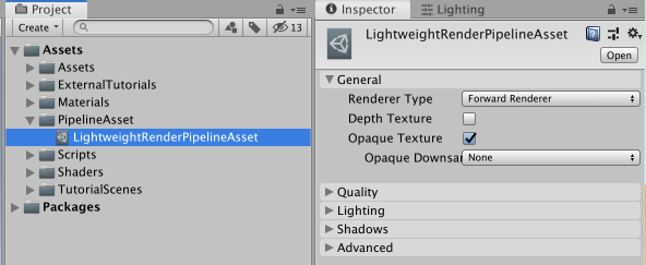
A Render Texture is a texture that is generated at runtime by a camera. This texture consists of what the camera sees. To use it you need to make some arrangements in your render pipeline.
Click your pipeline asset and switch on the Opaque Texture in the General section of the pipeline asset.
Glass Shader
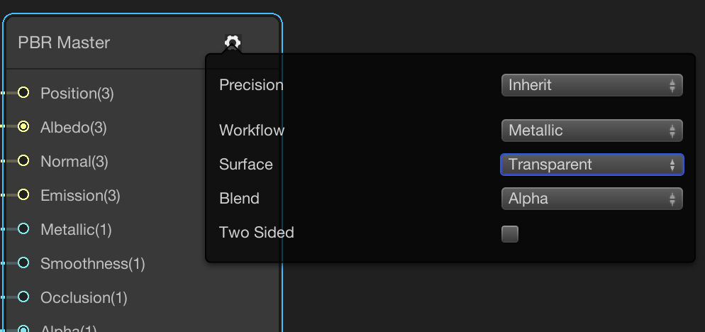
Create a PBR graph and call it GlassShader. Then change the Surface mode to Transparent from the gear icon at the top of the PBR Master Node.
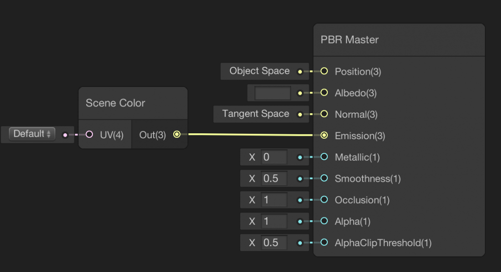
Let’s add a Scene Color Node. Scene Color Node will have the information that the camera is rendering. In other words, it provides access to the camera’s color buffer. Connect the output of the Scene Color Node to the Emission port of the PBR Master Node. Before checking the current shader, set Albedo to a darker color.
This is the result of this shader:
In order to give some photorealism to this shader, we should implement refraction.
Refraction

The direction of the light changes when it passes from one medium to another medium. For example, in the image above, you see a glass of Turkish tea and the spoon in the glass as if it is broken. This is because of refraction.
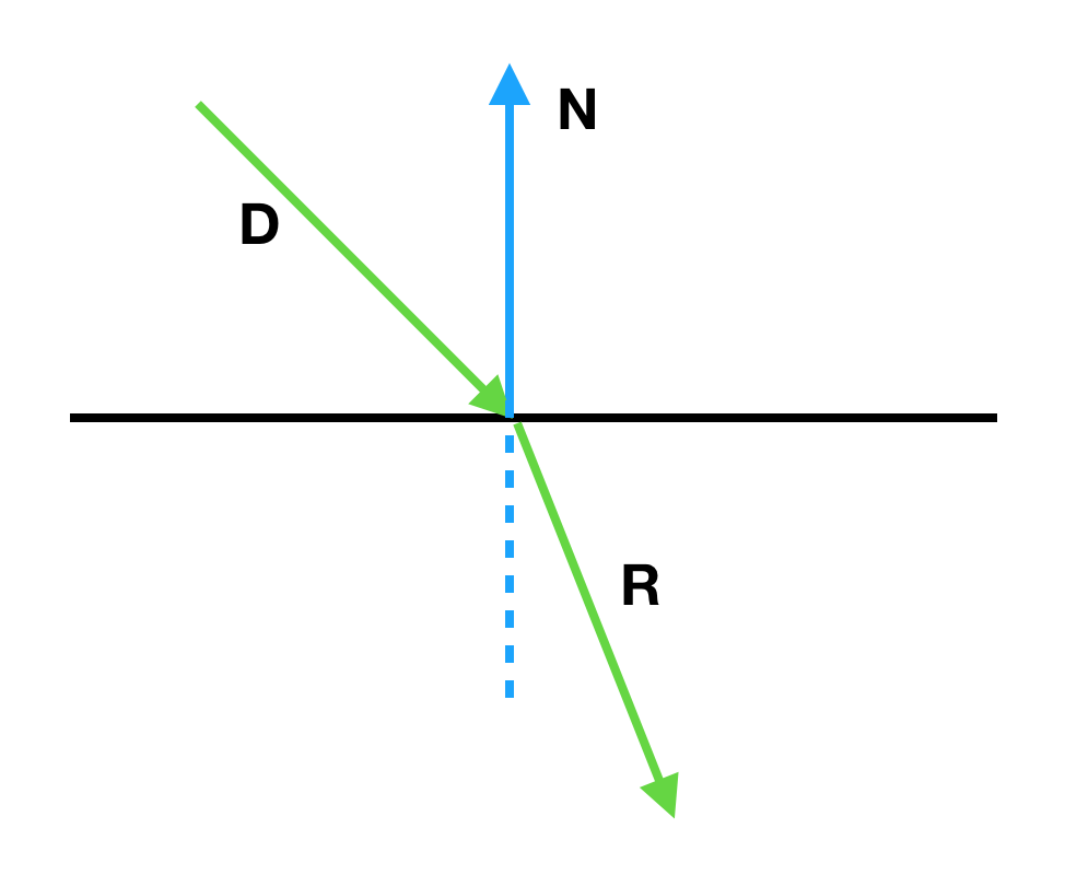
Refraction direction depends on the normal vector of the fragment, the direction of the incoming light and index of refraction. Index of refraction is an index that is described as the refraction ratio when the light passes one medium to another. And this also depends on the optical properties of two mediums.
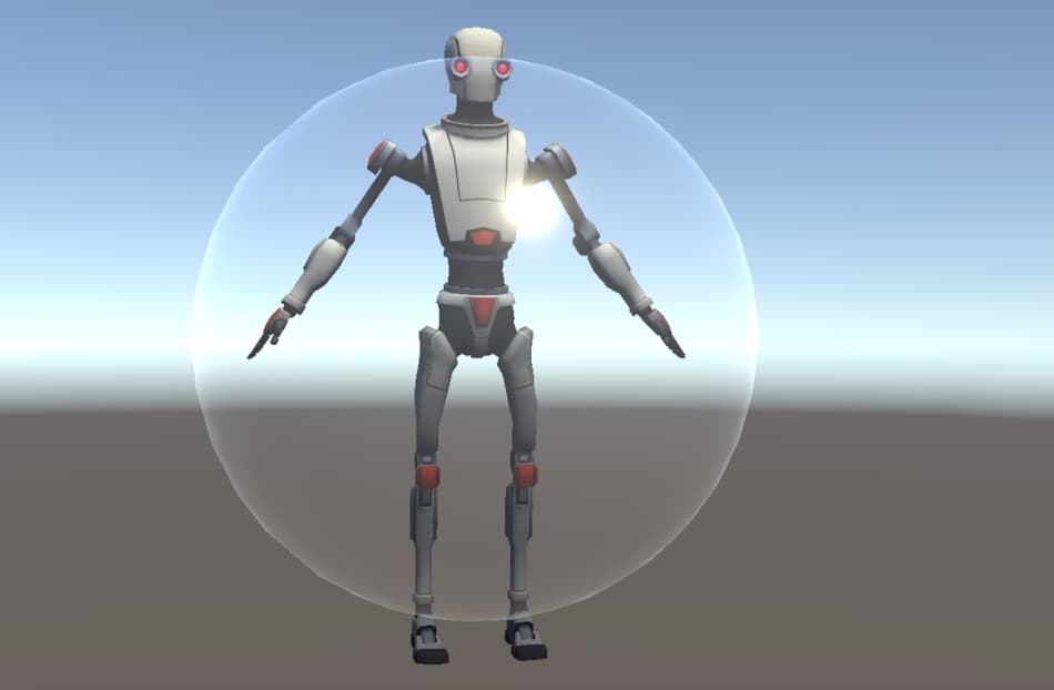
By default, Scene Color Node uses the screen positions as UV. For instance, in the image above, assume that the position of the Robot Kyle’s right eye is (500,500). In the case of refraction, we may see its position at (530,530). In other words, there is a shift in the positions of the fragments. What we are going to do is to calculate the refraction direction and add it to the current position of the fragment in order to obtain the shift.
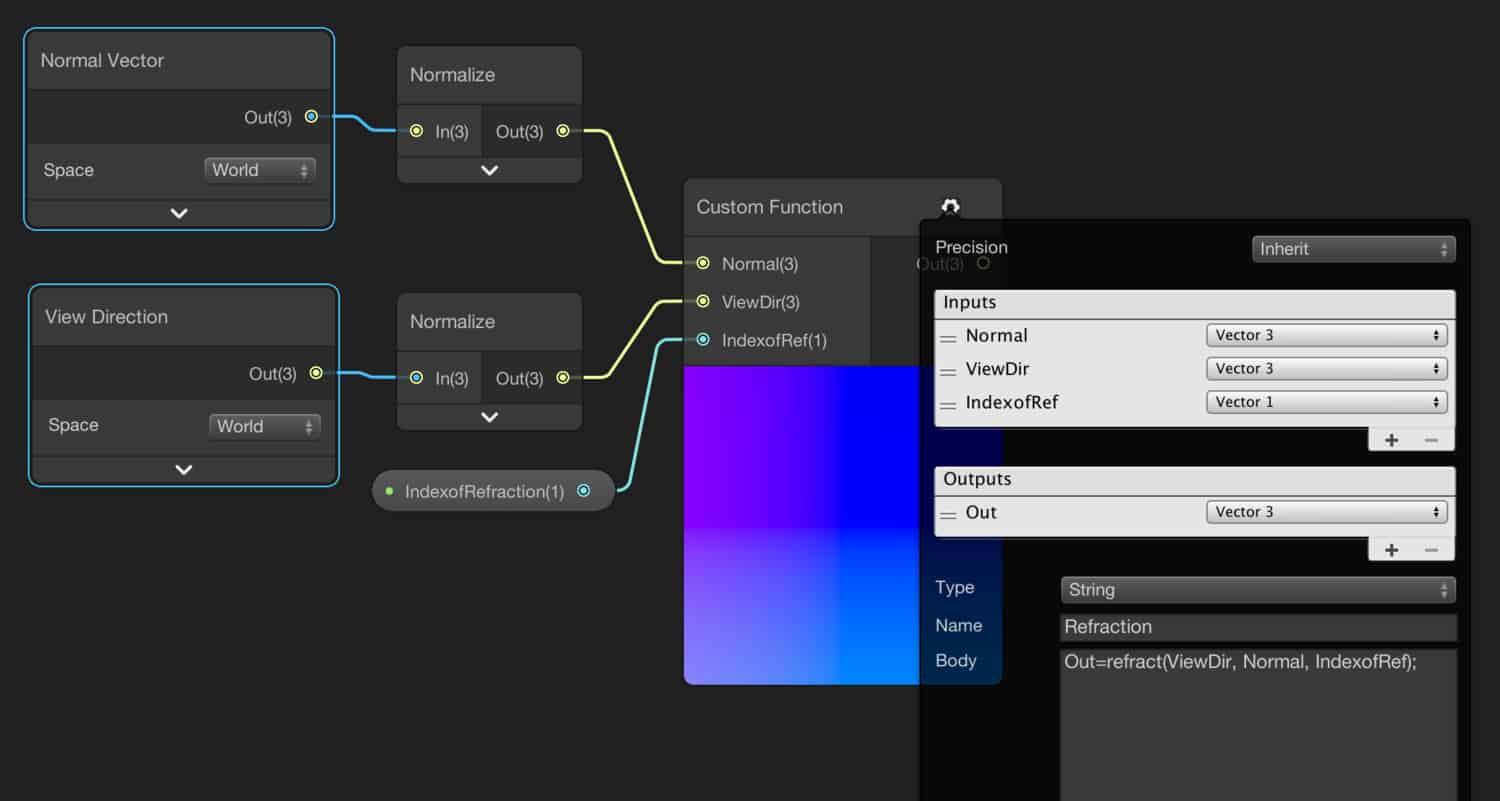
To calculate the refraction direction, we need normal vector, view direction and index of refraction. The index of refraction is a value that is determined by the person who will use this shader. Therefore, we should create a property for the index of refraction in Vector1 form. For the normal vector and the view direction vector, add a Normal Vector Node and a View Direction Node. Both of them have to be in world space.
In shader graph, there is no node to calculate refraction. However, Cg/HLSL has one. Therefore, at this point, we need to use a Custom Function Node to implement refraction.
In order to calculate refraction direction, we will you the following Cg/HLSL function. You can click here to access NVidia’s Cg documentation.
Out=refract(ViewDir, Normal, IndexofRef);
In addition to these, you have to normalize the View Direction and Normal Nodes before connecting them to the Custom Function Node.
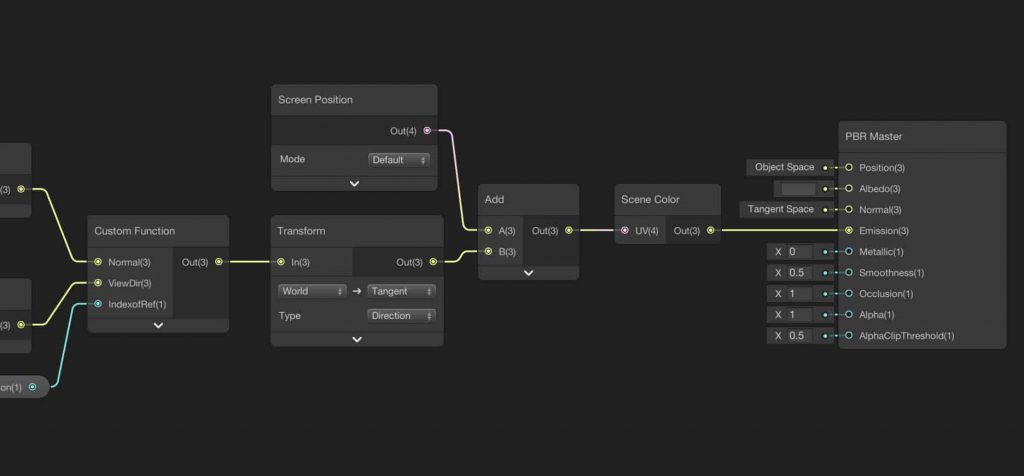
The output of the Custom Function Node gives us the reflection direction in world space. We need to transform it into the tangent space. We can do this by using a Transform Node. In the Transform Node, you should also select vector type as Direction, since refraction vector represents a direction. Therefore, we have obtained the refraction. This is the shift amount that will create the illusion of refraction. And we have to sum this shift amount with the screen position coordinates. To do this we will use a Screen Position Node and an Add Node.
And this is the result of this shader:
Nonsmooth Glass Shader
In this part, we are going to add a normal map to our glass shader to create glass that has not a smooth surface, i.e. brushed or deformed.
To implement such a property, we can use a normal map. By using a normal map, we change the normal directions of fragments according to the normal map, and therefore new normals are used in refraction function.
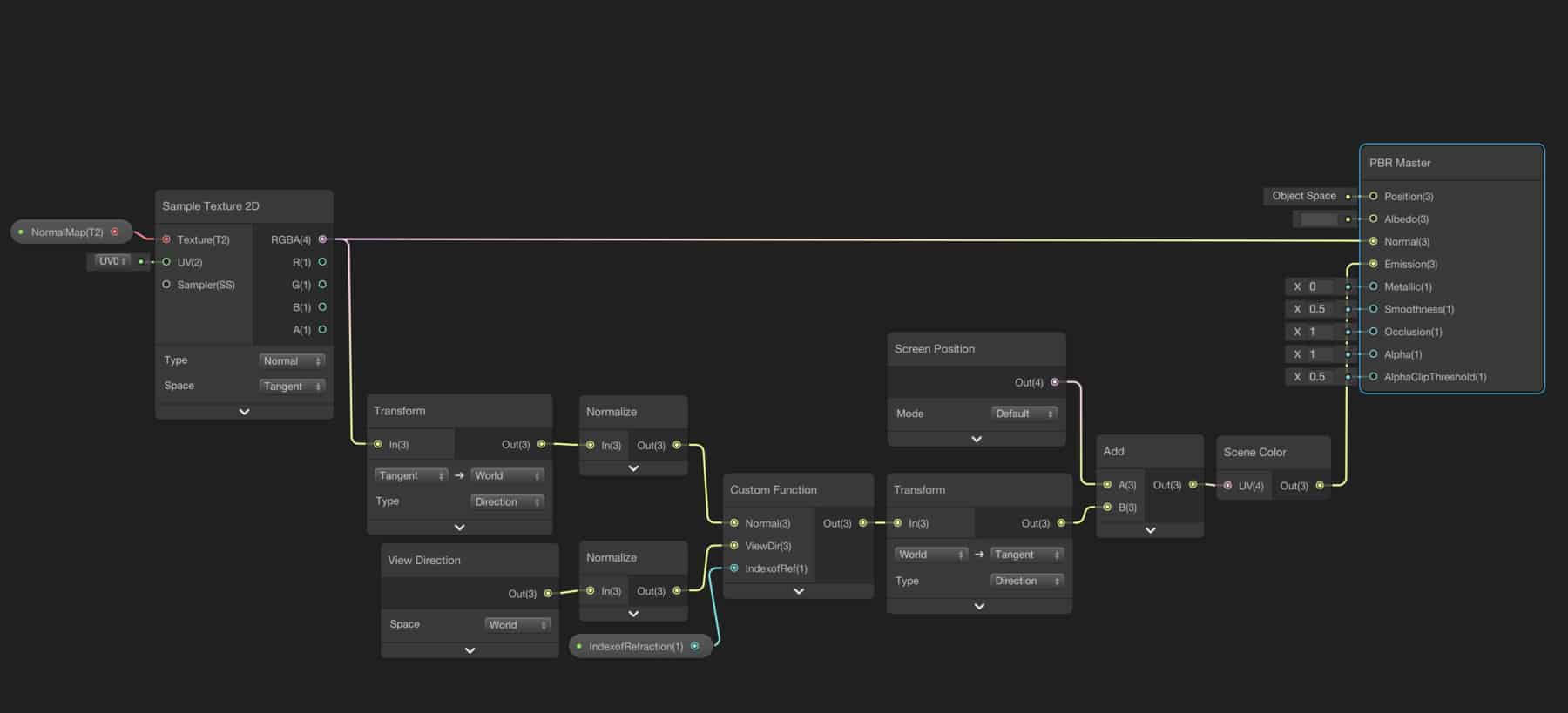
In order to use a normal map, add a new Texture2D property and use a Sample Texture2D Node to map the normal texture to our object’s UVs. Since this vector is in tangent space we have to find the representation of this normal vector in world space. To do this, use a Transform Node. We will use these new normals instead of the previous Normal Vector Node. Also, we need to connect the output of the Sample Texture2D Node to Normal port of the PBR Master Node. This last action is to increase photorealism by using this new normal for reflections. Our final shader should look like this.
You can test your shader by using any normal map. This is the result which I see.
It works just fine. It’s awsome. With this this I just remade the glass shader from HDRP. Wondering if I could find a cloaking effect shader here.
Hi!
I am not sure what a cloaking effect is. Is the following similar that you are looking for?
https://miro.medium.com/max/1266/1*_5VhuvxDWAh-VC9Ca5Mzxw.png
Hello, seems to be a great tutorial but i cannot make it works. The PBR is set to transparent but the material still opaque.
Hello, please be sure you have switched on the opaque texture option in the pipeline asset. If this does not solve the problem, it can be about a version related problem. In this tutorial, 2019.2.1 is used.