
Vertex Manipulation using Shader Graph in Unity3D
In this tutorial, we are going to see how we can manipulate the positions of the vertices of an object. Vertex manipulation allows us to modify the geometry of the rendered image. This is an example of what we can achieve by manipulating vertices.
A Quick Overview of Rendering Pipeline
A 3D model is nothing but only a set of mathematical coordinates of vertices in 3D space. When CPU wants to show you something it tells GPU to draw it. This is called a drawcall. GPU takes the mathematical coordinates of the model and locates them into the required positions. This stage of the rendering pipeline is called as Vertex Shader stage. Then these positions are connected with lines. This process is done by the rasterizer. Finally, in Fragment Shader stage, pixels which belong to that model are colorized. (Actually, neither this is the final stage of the rendering pipeline nor all the graphics pipeline is so basic, but for our purpose here, this brief overview is sufficient).
Up to now, in our previous shader graph tutorials, we only dealt with the pixel colors. And these tutorials actually were about Fragment Shaders(even though we did not talk about it). When we want to manipulate positions of the vertices, we dealt with vertex shaders. On the other hand, Shader Graph hides all these shader stages make it easy to develop shaders. Hence, you do not need to worry about the graphics rendering pipeline much.
As we mentioned in our previous tutorials, shaders work simultaneously for each pixel. This is the same for vertices also. Vertex shaders are executed in parallel for each vertex. Therefore, we should assume that we are creating our shaders for each pixel and each vertex individually. We are going to check the positions of the pixels and if they satisfy with our request, we are going to modify their locations in runtime.
A Basic Vertex Manipulation Example
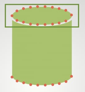
Let’s start with a basic example. In this first example, we are going to change the positions of the vertices of a cylinder’s top and bottom bases. And hence, we may make the cylinder taller or shorter.
First, let’s determine which vertices are on the top base of the cylinder. To do this, we can check if the y-component of the position of the vertex is greater than 0. If so, we can add displacement amount in the y-direction to its initial position.
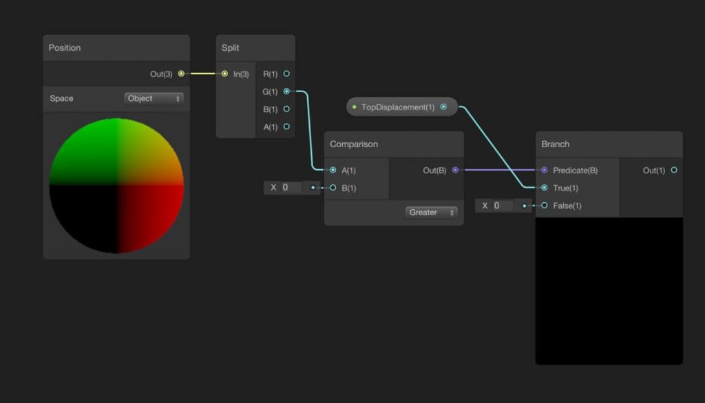
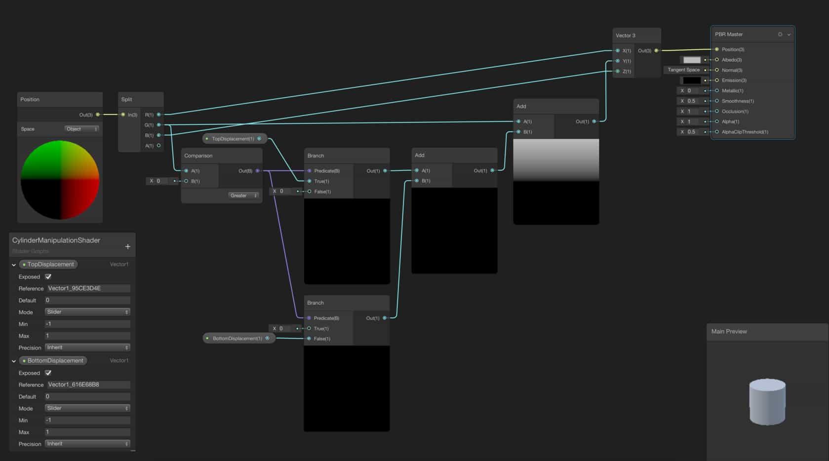
Start by adding a Position Node and using a Split Node, obtain the y-component of the position. Do not forget to change the Space to Object in the Position Node. By using a Comparison Node, we can check if the y-position of the vertex is greater than 0. Then we can convert the output of the Comparison Node to a mathematical value using a Branch Node. It is a good idea to create a TopDisplacement property and connect it to the True port of the Branch Node. Therefore, we will get the displacement amount for the upper base of the cylinder from the output of the Branch Node.
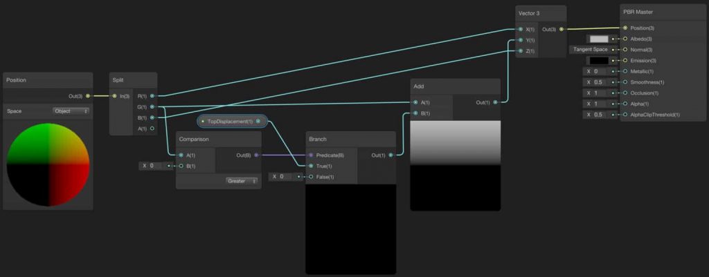
Since we already obtain the displacement amount for the vertices on the upper half of the object, now we can set their displacement from the initial position. For our purpose, we only change the position in the y-direction. To do this, add the obtained displacement amount to the y-component of the initial positions. Since we have to represent the positions in 3D Space with a 3D vector, we have to construct it. To construct a 3D vector, add a Vector 3 Node to the shader graph. Connect the x and z components as is and y component as the output of the Add Node. Then connect the output of the Vector 3 Node to the Position port of the PBR Master Node.
Let’s go a step further and do the same thing for the bottom base. Add a new property for the bottom displacement. In addition, you should add a new Branch Node and a new Add Node. For the upper part of the cylinder, we have used the True port of the Branch Node. This time, we will use False port. By adding the outputs of the two Branch Nodes, we will get a displacement amount for each vertex. If the y-component of a vertex is greater than zero, the top base will move otherwise, the bottom base will move.
Another Vertex Manipulation Example: Animating A Flag
In this part of the tutorial, we are going to continue examples of vertex manipulation. This time we are going to animate a flag. I used this great flag model in this shader and you may use it or you may find another model, instead.
First, create a Texture2D property and map it to the model. Here, we will not talk about this. But if you would like to see how texture mapping works, you can follow this link to see our Shader Graph tutorials.
The motion of a flag on a windy day is very close to a traveling sine wave. The mathematical function of a traveling sine wave is given by the following equations:
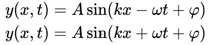
While the first one represents a wave that is traveling to the right, the latter represents a wave that is traveling to the left. Here, position in the y-axis is a function of position in the x-axis and time. In addition, A, k, w represent amplitude, wave number, and angular velocity, respectively.
We are going to manipulate y-components of the positions of the vertices according to their x-components. Even though this kind of mathematical expressions can be constructed by using only Shader Graph nodes, this will create a mess since there are several nodes for only one mathematical function. Instead of using several nodes, it is a good idea to use Custom Function Node for this kind of mathematical expressions.
The procedure to create a Custom Function Node is the same for any other node. Just right click on the Shader Graph screen and choose “Create Node”, then search for Custom Function Node.
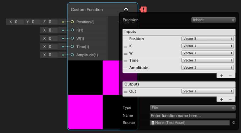
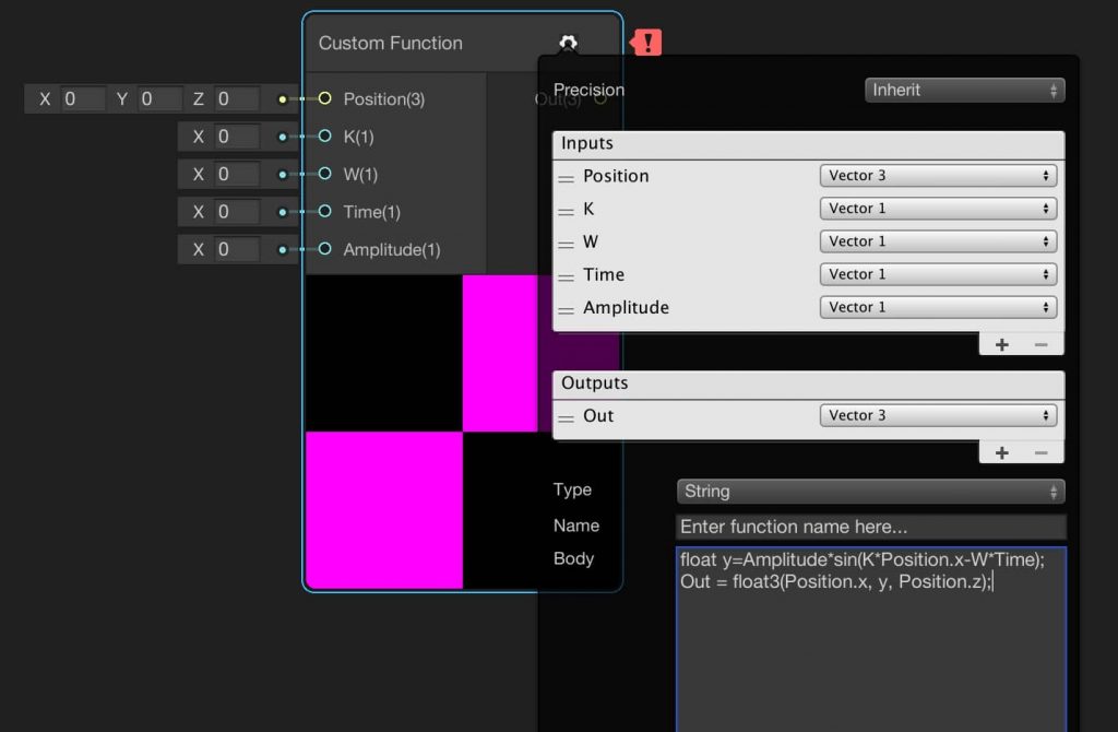
Custom Function Node gives us the opportunity to create our own nodes which we can also determine inputs and outputs. Here we should create inputs and outputs as in the image above.
We have two options here. We can execute a function in a file or write our function inside the node. Since we want to write our function inside the node, choose String from the Type selection. Then write the code below into the Body section.
float y=Amplitude*sin(K*Position.x-W*Time);
Out = float3(Position.x, y, Position.z);
You should also give a name to your function. Your node should look like this:
Arrange your shader as follows:
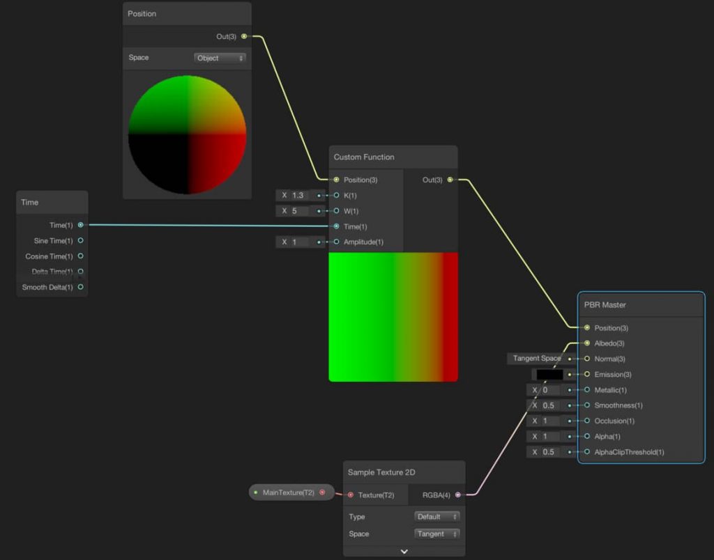
And this is the result:
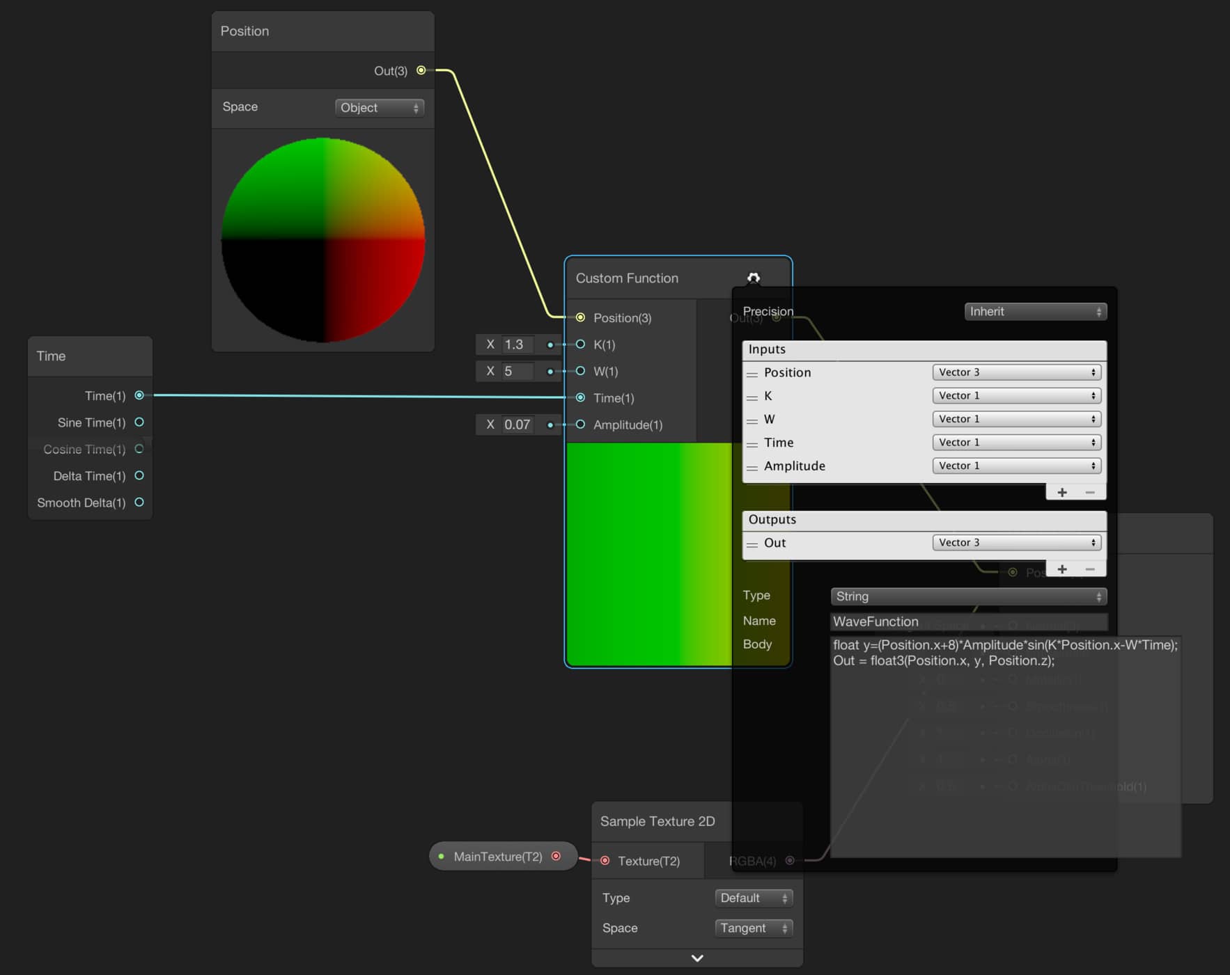
There is a problem in this animation. The amplitude of the waves should increase from left to right. To obtain this behavior, update your function as follows:
float y=(Position.x+8)*Amplitude*sin(K*Position.x-W*Time);
Out = float3(Position.x, y, Position.z);
In order to make the left edge steady, we need to make y position 0 at those points. Since our model’s pivot point is set at the center of the model and since we are working on object space, in order to obtain 0 at the left edge we sum x-component of the position and 8. If you are using an object other than the model which is used here, you should change the numbers that suit your needs.
Final shader will be like the following:
And this is the final result:
In this article, we have learned how we can manipulate positions of vertices and see two examples of vertex manipulation.
Really nice explanation.. really like ur stuff