Shader Pass and Multi-Pass Shader
In the previous article, we have seen texture mapping in Unity Cg/HLSL shaders. We will continue our journey with shader passes. In this article, we will see what a shader pass is and learn how we use shader passes in our shaders.
Contents
What is a shader pass?
When CPU wants to draw an image of a model on the screen, it makes a request from GPU to render the model(drawcall). When an image is rendered on the screen this is called a pass. If there are two images rendered, the pass count is two. If you do not understand, do not worry, just keep reading, you will understand within a few minutes if you follow the tutorial.
Rendering more than one image from a mesh
As you may see in our previous shaders, we declare pass blocks inside a subshader block. Up to now, there is only one Pass in our shaders. This is because we only wanted to draw only one image from models. Now as an example, we will draw two images from a model. Let’s get started.
As usual, begin by duplicating the BasicShader(or copy from the link). Change its name to MultiPassShader. You should also change the first row of the shader code.
Shader "AdvancedShaderDevelopment/MultiPassShader"
We will paint the rendered images to different colors. Therefore, we need to add two property for two colors. Change the Properties block as follows:
Properties
{
    _FirstColor("First Color", Color)=(1,0,0,1)
    _SecondColor("Second Color", Color)=(0,1,0,1)
}
Then, copy the entire Pass block and paste it to just below the first one. We will play with the both of the Pass blocks independently. Add the _FirstColor and _SecondColor properties as variables to first and second passes, respectively.
This shader will work in this situation but we cannot distinguish the two images since they are rendered top of each other. But if we render them different positions, we can distinguish them. Let’s shift both images to right and left a little bit.
v2f vert (appdata v)
{
    v2f o;
    v.vertex-=float4(1.5,0,0,0);
    o.clipPos=UnityObjectToClipPos(v.vertex);
    return o;
}
Modify the vertex function in the first pass as above. Thereby, this image will be shifted to the left. To shift the second image to right you should use a plus sign instead of minus in the vertex function in the second pass.
Entire shader code should look like this:
Shader "AdvancedShaderDevelopment/MultiPassShader"
{
    Properties
    {
        _FirstColor("First Color", Color)=(1,0,0,1)
        _SecondColor("Second Color", Color)=(0,1,0,1)
    }
    SubShader
    {
        Pass
        {
            CGPROGRAM
            #pragma vertex vert
            #pragma fragment frag

            #include "UnityCG.cginc"

            fixed4 _FirstColor;

            struct appdata
            {
                float4 vertex:POSITION;
            };

            struct v2f
            {
                float4 clipPos:SV_POSITION;
            };

            v2f vert (appdata v)
            {
                v2f o;
                v.vertex-=float4(1.5,0,0,0);
                o.clipPos=UnityObjectToClipPos(v.vertex);
                return o;
            }

            fixed4 frag (v2f i) : SV_Target
            {
                return _FirstColor;
            }
            ENDCG
        }

        Pass
        {
            CGPROGRAM
            #pragma vertex vert
            #pragma fragment frag

            #include "UnityCG.cginc"

            fixed4 _SecondColor;

            struct appdata
            {
                float4 vertex:POSITION;
            };

            struct v2f
            {
                float4 clipPos:SV_POSITION;
            };

            v2f vert (appdata v)
            {
                v2f o;
                v.vertex+=float4(1.5,0,0,0);
                o.clipPos=UnityObjectToClipPos(v.vertex);
                return o;
            }

            fixed4 frag (v2f i) : SV_Target
            {
                return _SecondColor;
            }
            ENDCG
        }

    }
}
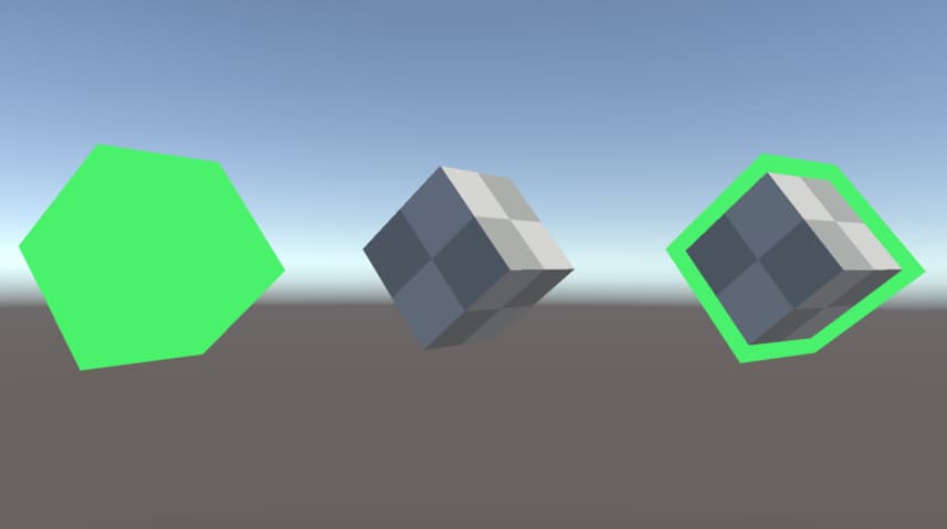
And this is the result of this shader.
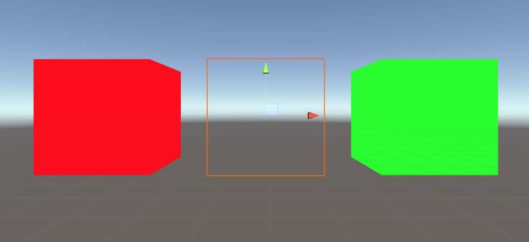
As you see, we have a cube which is originally located at the center of the image. However, we are able to render two copies and change the positions of images.
Both passes have their input and output structs, and vertex and fragment functions. Calling to draw this cube is one Draw call. On the other hand, drawing two images from the same cube is two SetPass calls.
Creating an outline shader
Now, let’s make an example for multiple passes by creating an outline effect shader for basic meshes. This time we will construct our shader by using TextureMappingShader as a base. Therefore duplicate the TextureMappingShader or copy from the link above and paste to a new shader file. Change its name to OutlineShader.
As usual, the first thing which we do is to change the first row.
Shader "AdvancedShaderDevelopment/OutlineShader"
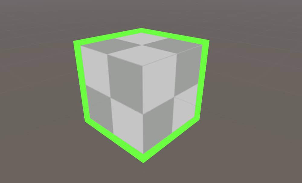
We will render two copies of the same mesh and combine them as the image above. We would like to be able to control the color and size of the outline. Therefore add two new properties to Properties block one for outline color and one for outline size.
Properties
{
    _MainColor("Main Color", Color)=(1,1,1,1)
    _MainTexture("Main Texture", 2D)="white"{}
    _OutlineColor("Outline Color", Color)=(1,1,1,1)
    _OutlineSize("OutlineSize", Range(1.0,1.5))=1.1
}
In the code above, we used Range(min, max) function instead of specifying the property _OutlineSize as Float. This will allow us to clamp the size between two values and control using a slider in the material inspector, as well.
To create an outline, copy the entire Pass and paste it below the original one. In this pass we will not need variables _MainTexture and _MainColor but we will use _OutlineColor and _OutlineSize, instead. Furthermore, we do not need UVs in vertex and fragment functions, hence it is a good idea to remove UV related variables and operations in structs and functions.
In this pass, fragment function will only return a plain color which is _OutlineColor. Since we want the object is a little bigger, we need to multiply vertex positions with the _OutlineSize.
o.clipPos=UnityObjectToClipPos(v.vertex*_OutlineSize);
The second pass should look like this:
Pass
{
    CGPROGRAM
    #pragma vertex vert
    #pragma fragment frag

    #include "UnityCG.cginc"

    fixed4 _OutlineColor;
    float _OutlineSize;

    struct appdata
    {
        float4 vertex:POSITION;
    };

    struct v2f
    {
        float4 clipPos:SV_POSITION;
    };

    v2f vert (appdata v)
    {
        v2f o;
        o.clipPos=UnityObjectToClipPos(v.vertex*_OutlineSize);
        return o;
    }

    fixed4 frag (v2f i) : SV_Target
    {
        return _OutlineColor;
    }
    ENDCG
}
When we use this shader to render an object, we will not see two rendered images but instead only one bigger object. This is because the main rendered image will be located inside the outline. There are a few solutions to this problem but let’s see the easiest one.
When GPU renders a mesh, we can decide both faces are rendered or only one face is rendered. This method is used for optimization purpose and it is called Culling. In our case, for the second pass, we can tell the GPU not to render front faces. Thus, the front face of the outline will not be visible and we will see the main object behind the outline. Moreover, since the back faces are rendered we will see the outline.
In order to make the front faces invisible, we use keyword Cull Front. Add this keywords inside the second pass before CGPROGRAM code block.
This is the full code of OutlineShader:
Shader "AdvancedShaderDevelopment/OutlineShader"
{
    Properties
    {
        _MainColor("Main Color", Color)=(1,1,1,1)
        _MainTexture("Main Texture", 2D)="white"{}
        _OutlineColor("Outline Color", Color)=(1,1,1,1)
        _OutlineSize("OutlineSize", Range(1.0,1.5))=1.1
    }
    SubShader
    {
        Pass
        {
            CGPROGRAM
            #pragma vertex vert
            #pragma fragment frag

            #include "UnityCG.cginc"

            fixed4 _MainColor;
            sampler2D _MainTexture;
            float4 _MainTexture_ST;

            struct appdata
            {
                float4 vertex:POSITION;
                float2 uv:TEXCOORD0;
            };

            struct v2f
            {
                float4 clipPos:SV_POSITION;
                float2 uv:TEXCOORD0;
            };

            v2f vert (appdata v)
            {
                v2f o;
                o.clipPos=UnityObjectToClipPos(v.vertex);
                o.uv=(v.uv*_MainTexture_ST.xy)+_MainTexture_ST.zw;
                return o;
            }

            fixed4 frag (v2f i) : SV_Target
            {
                fixed4 col;
                col=tex2D(_MainTexture, i.uv)*_MainColor;
                return col;
            }
            ENDCG
        }

        Pass
        {

            Cull Front

            CGPROGRAM
            #pragma vertex vert
            #pragma fragment frag

            #include "UnityCG.cginc"

            fixed4 _OutlineColor;
            float _OutlineSize;

            struct appdata
            {
                float4 vertex:POSITION;
            };

            struct v2f
            {
                float4 clipPos:SV_POSITION;
            };

            v2f vert (appdata v)
            {
                v2f o;
                o.clipPos=UnityObjectToClipPos(v.vertex*_OutlineSize);
                return o;
            }

            fixed4 frag (v2f i) : SV_Target
            {
                return _OutlineColor;
            }
            ENDCG
        }

    }
}
And this is the result of this shader: