The Big Shader Graph Tutorial: Third Part
This is the third part of the Big Shader Graph Tutorial. In order to reach other shader graph tutorials, you can follow this link. In this part, we will learn transparency, animation, and differences between coordinate spaces.
Transparency
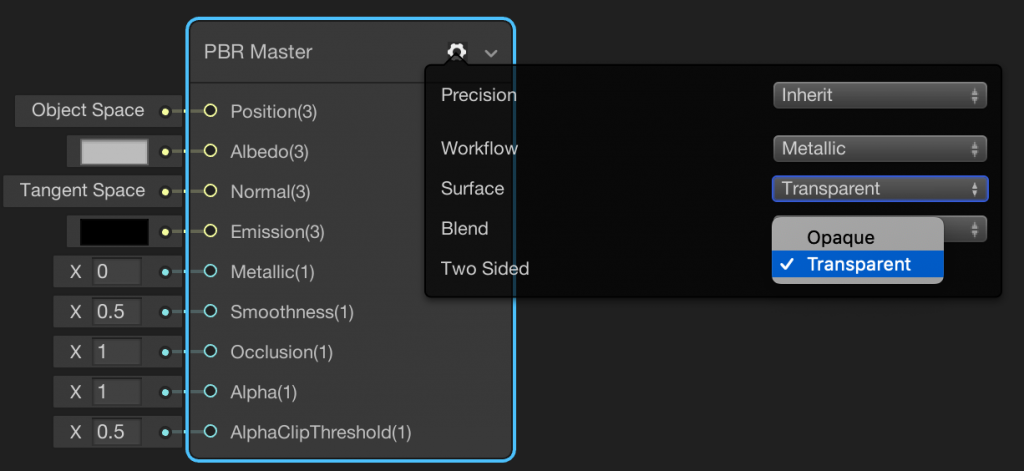
To create transparent or semi-transparent objects we have to set up the shader for this purpose. Create a new PBR shader using Shader Graph. Click the gear icon on the PBR Master Node and change the Surface Option to Transparent.
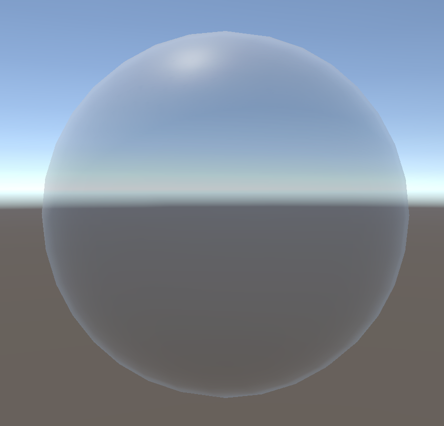
Changing the Alpha value affects the whole surface since we do not specify any certain pixel on the surface. For example, this shader will semi-transparent when we set the Alpha value to 0.5.
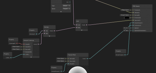
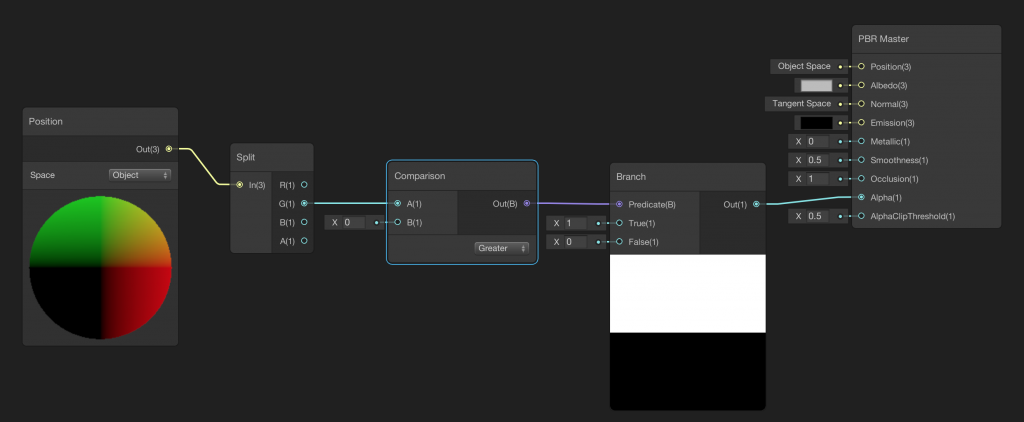
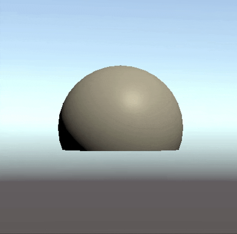
In addition to changing the alpha value for the whole surface, we can also set different alpha values to different pixels. As an example, imagine that we want to render a hemisphere. What we can do is to take a sphere and set the alpha value for the bottom hemisphere to 0 and 1 to the top hemisphere. Hence, we will render only half of the sphere.
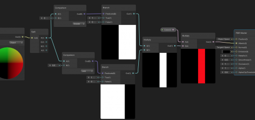
To do this, add a Position Node to determine the position of the pixel in the object space(remember that we always write shader programs as if only for one pixel). Then we need to check if it is in the bottom hemisphere or the upper hemisphere. If it is in the upper half, then we will set the alpha value to 1 otherwise 0.
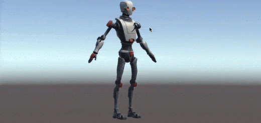
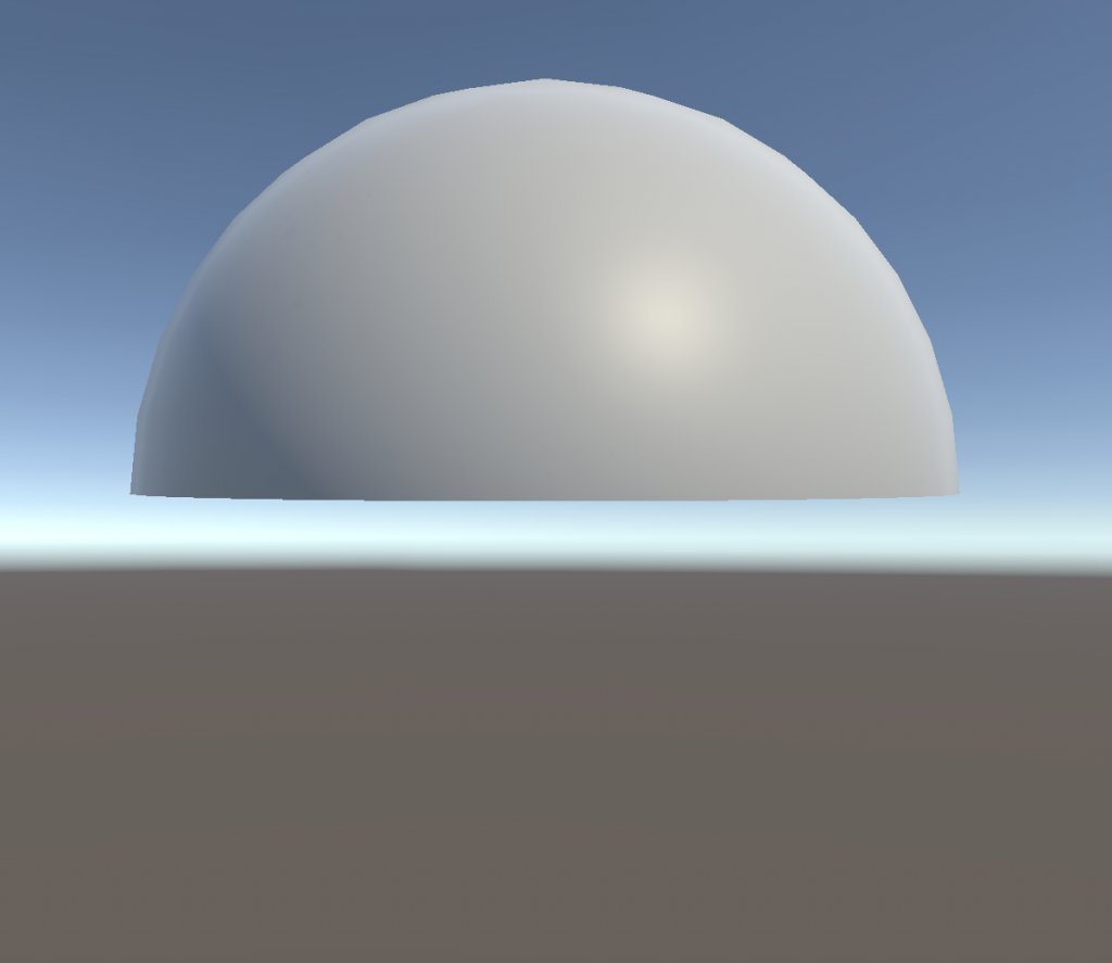
And this is the result:
You can also use a transparency map like a normal map to determine the alpha values for different pixels.
Coordinate Spaces and Difference Between Them
As we mentioned before, we create our shaders as if they are only for only one pixel. We write them like this but GPU executes shaders for each pixel and vertex, independently and simultaneously. For instance, by adding a Position Node, we specify only one pixel or a vertex position and make our calculations for it. For each pixel, this is done by GPU in parallel.
In Position Node, we specify the coordinate space that we want to work on. Here I am not going to make a formal definition for the term coordinate space. If you are curious about it, you may take a look at linear algebra books. But let’s explain how we use them briefly:
When you want to control the colors of pixels and positions of vertices according to positions relative to the object itself then you have to use object space coordinates. For instance, you want to change the color of the pixels between -0.1 and 0.1 in the x-direction according to the pivot point of the object (like we did in the previous tutorial). Then you have to use object space.
Now, imagine that we want to change pixel colors for pixels which are on a position relative to the center of the world (scene). In this case, we have to use world space coordinates.
What about if we want to manipulate pixel colors according to our point of view? In this case, we have to use view space coordinates.
Let’s demonstrate them in an example.
In the example above, we rendered a sphere as a hemisphere. We used object space coordinates to do this. We checked whether the pixel is greater than 0 or not and changed its transparency according to the result.
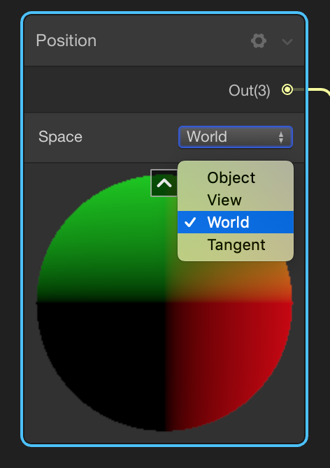
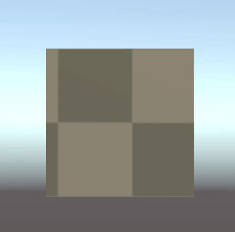
Now let’s use the same shader. But in this case select world space in the Position Node. Save the shader and observe what we obtained.
As you can see, the points of the object are not rendered when their y-coordinate are smaller than zero according to the scene’s center point.
Now change the coordinate space to view space and try to observe what you obtain.
Animating Colors
Shaders are memoryless. They forget what they do in the last millisecond. They do their job in one frame and forget it. Therefore we cannot animate things by adding their last action to the new one. But we can use the time to animate pixel colors or positions of the vertices. In this section of the tutorial, we will create a scrolling shader using Shader Graph.
The logic behind the scrolling shader is just changing the offset of the UV-mapping. We will use a Time Node to change the U or V value of the UV-map and therefore we are able to create a flow on the texture.
Create a new PBR shader using Shader Graph for this example. Add a Texture 2D Node and a Sample Texture 2D Node and connect them to the Albedo port of the PBR Master Node.
Add a Tiling and Offset Node. We can change the tiling and offset values using this node. For this example, we will use the offset option only. Imagine that we want a scrolling effect on the x-direction only. In this case, we have to change only the x-value of the offset. To do this we can construct a 2-dimensional vector and only change x value by time. The y-component must be 0. Add a Vector2 node. To change the x-component by time, add a Time Node. Connect the first port of the Time Node to the X input of the Vector2 Node.
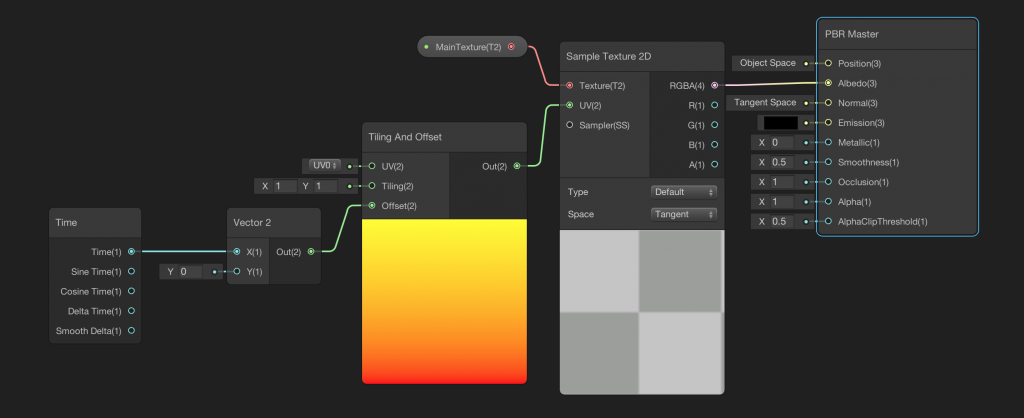
Save the shader and turn back to Unity Editor. Add a quad to your scene and also create a new material for this shader. Assign the material to the quad. When you press Play, you should see the scrolling effect in the x-direction.
If you would like to control the speed of the scrolling effect, you should multiply the output of the Time Node with a number then connect the output to Vector2. Likewise, if you would like to change the flow in the opposite direction, you should multiply the output of the Time Node with a negative value. Another thing which you can do is to add a property for flow speed. If you use this property for multiplication then you will be able to control the speed of scrolling from the Unity Editor.