Texture Mapping in Cg/HLSL
In the previous article, we have seen the fragment shader. We also worked on several fragment shader examples that reinforce our knowledge of pixel color manipulation. In this article, we will see how we can wrap an object with a texture to make the object realistic. Texture mapping is an important part of shader development.
Contents
- Why do we need textures?
- UV Space
- How do we map textures in Unity3D?
- Tiling and offset
- Texture animation
Why do we need textures?
In real life, every object has a texture. If you want your object to be seen unique, distinguishable from other objects on a computer screen, then you should wrap it with a texture.

Look at the image on the right. You can distinguish the fabric part and wooden part of the chair. There are two reasons that you can distinguish them, and easily say which part is fabric and which part is wooden. The first reason is the material properties which cause how they reflect the light. We will see how we model these material properties while implementing lighting models into our shaders. The second reason is the texture of the piece of the model. Textures have a great impact on how an object is seen on the computer screen. For instance, if you assign a wood texture on a car, this will probably break the photorealism.
UV Space
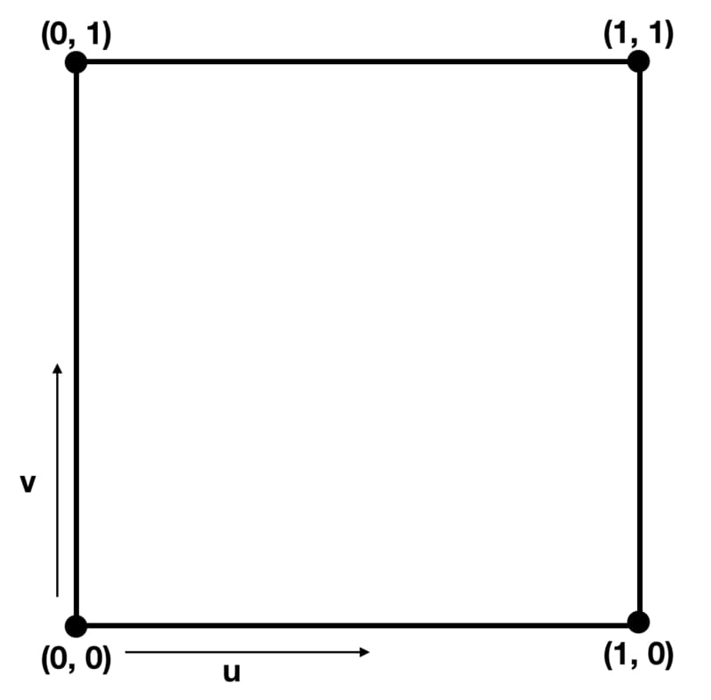
We have already mentioned the UV space briefly before. Here, let’s make a deeper explanation here. UV Space is 2D rectangular coordinate system that is used for texture mapping. The coordinates on the UV space are clamped between 0 and 1 in both u and v directions. If you are not familiar with 3D modeling I am sure you are confused. However, there is no reason to be confused. You can visualize UV space as a square. Let the bottom left corner of the square’s coordinates is (0,0) and the top right corner is (1,1). This is the borders of the UV Space. Every position outside of this square is invalid for UV space. And every position inside of this square will has a value between 0 and 1.
How do we map textures in Unity3D?
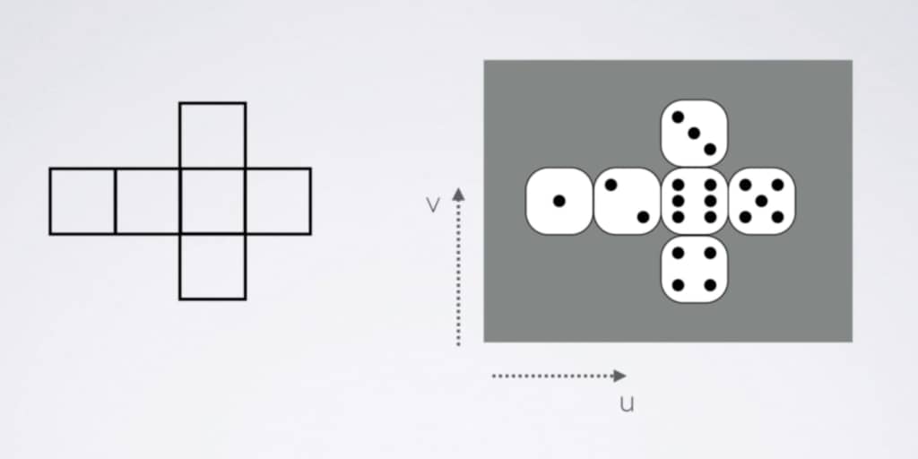
Consider the layout of a cube. If you map each point on the layout onto the texture on the right, you will get a die. Thus, all the points on the layout will have a color value. This mapping operation is called texture mapping or UV mapping. Which point on the surface of the 3D mesh is mapped on the square(UV Space) is exported from the 3D model creation software like Maya or Blender. The UV information is stored in vertices. In Unity, you can either use these coordinates or manipulate them as you want. In this part of the article, we will see how we can map a texture on an object. In the next part, we will manipulate the UV coordinates and animate this texture. Let’s get started.
Duplicate the BasicShader or create a new shader and copy-paste the shader code in the BasicShader example. Change the name of the shader as TextureMappingShader. As usual, change the first row the shader.
Shader "AdvancedShaderDevelopment/TextureMappingShader"
Since we will assign a texture (a 2D texture image) from outside of the shader, we have to declare that in Properties block. Therefore, add a _MainTexture property as follows.
Properties
{
  _MainColor("Main Color", Color)=(1,0,0,1)
  _MainTexture("Main Texture", 2D)="white"{}
}
Furthermore, in order to connect ShaderLab and Cg/HLSL, we have to declare variables, that have the exact same name with the properties, in the CGPROGRAM code block.
CGPROGRAM
....
....
  fixed4 _MainColor;
  sampler2D _MainTexture;
.....
.....
ENDCG
Observe that the data type of texture in ShaderLab is 2D and the data type of it in Cg is sampler2D.
As mentioned, UV data is stored in vertices. Therefore, in order to pass this data to fragment shader, we have to assign it to the input of the fragment shader (as mentioned, this is also the output of vertex shader). This means that we have to indicate we will use UV data in vertex and fragment shaders. This is done in appdata and v2f structs as below.
struct appdata
{
    float4 vertex:POSITION;
    float2 uv:TEXCOORD0;
};

struct v2f
{
    float4 clipPos:SV_POSITION;
    float2 uv:TEXCOORD0;
};
As mentioned before, as well, TEXCOORD shader semantics keyword is used to store position and texture coordinate data.
For now, in fragment shader we will use UV data as exported from 3D model creation software as is, without any manipulation. To do this, we will pass the UV coordinates to the output of the vertex shader as is.
v2f vert (appdata v)
{
    v2f o;
    o.clipPos=UnityObjectToClipPos(v.vertex);
    o.uv=v.uv;
    return o;
}
Finally, we have the UV data in fragment shader. Now, it is time to map the _MainTexture onto the UV coordinates. In Cg, there is a built-in function that does this job for us. It is tex2D( ). This function takes texture and UV data and returns a color value for individual fragments.
fixed4 frag (v2f i) : SV_Target
{
    fixed4 col;
    col=tex2D(_MainTexture, i.uv);
    return col;
}
This is the complete shader code up to now:
Shader "AdvancedShaderDevelopment/TextureMappingShader"
{
    Properties
    {
        _MainColor("Main Color", Color)=(1,0,0,1)
        _MainTexture("Main Texture", 2D)="white"{}
    }
    SubShader
    {
        Pass
        {
            CGPROGRAM
            #pragma vertex vert
            #pragma fragment frag

            #include "UnityCG.cginc"

            fixed4 _MainColor;
            sampler2D _MainTexture;

            struct appdata
            {
                float4 vertex:POSITION;
                float2 uv:TEXCOORD0;
            };

            struct v2f
            {
                float4 clipPos:SV_POSITION;
                float2 uv:TEXCOORD0;
            };

            v2f vert (appdata v)
            {
                v2f o;
                o.clipPos=UnityObjectToClipPos(v.vertex);
                o.uv=v.uv;
                return o;
            }

            fixed4 frag (v2f i) : SV_Target
            {
                fixed4 col;
                col=tex2D(_MainTexture, i.uv);
                return col;
            }
            ENDCG
        }
    }
}
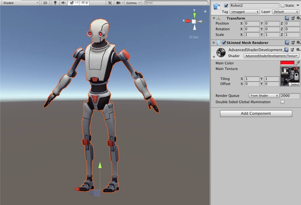
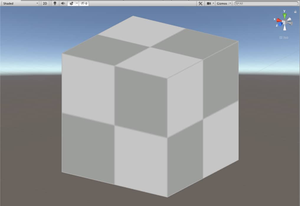
This shader looks like the following. You can click here to see the Asset Store page of this model.
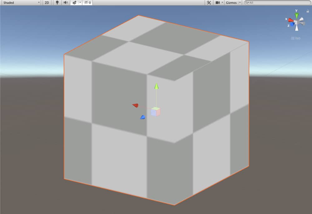
And this is the same shader with checkered texture on a cube.
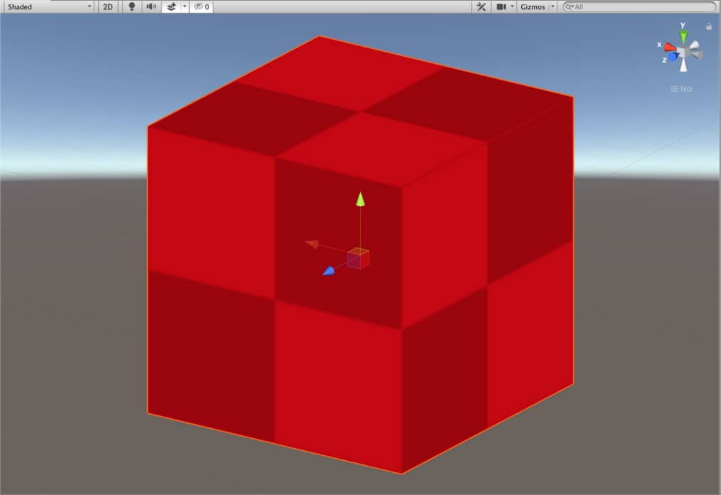
We can add a color tint using _MainColor property, as well. To do this, multiply the _MainColor with the tex2D( ) function.
fixed4 frag (v2f i) : SV_Target
{
    fixed4 col;
    col=tex2D(_MainTexture, i.uv)*_MainColor;
    return col;
}
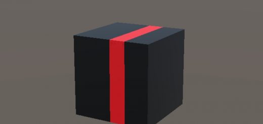
This is the same cube with a red tint.
Tiling and offset
As told above, we do not have to use the UV coordinates as exported from the model creation software and we can play with it. For instance, we can set a tiling or offset values either u or v coordinates.
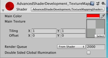
Whenever you add a texture to a shader, tiling and offset properties are added automatically and it is visible in material inspector.
Since we have implemented neither tiling nor offset properties to our shader, they have no function now. In order to implement, these properties into our shader, first we have to declare a new variable in CGPROGRAM code block. Add a _MainTexture_ST variable which is in float4 type.
CGPROGRAM
....
....
  fixed4 _MainColor;
  sampler2D _MainTexture;
  float4 _MainTexture_ST;
.....
.....
ENDCG
This new variable is a 4 dimensional vector. The x and y are used for tiling. z and w components, on the other hand, are used for offset.
If we want to play with UV coordinates, we have to do this before the rasterizer stage. In other words, we need to implement these into vertex shader. If you modify vertex shader as following, you will change the tiling of the texture.
v2f vert (appdata v)
{
    v2f o;
    o.clipPos=UnityObjectToClipPos(v.vertex);
    o.uv=v.uv*_MainTexture_ST.xy;
    return o;
}
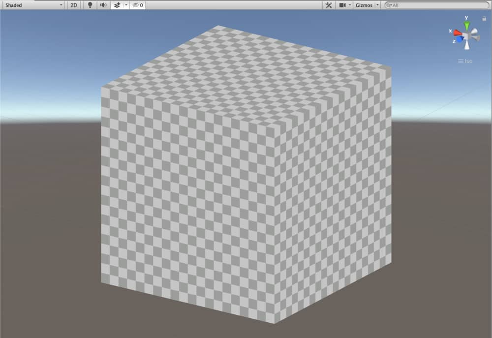
When I set x and y value of tiling property in material inspector to 10, I obtain the following result.
To implement the offset property, we need to modify vertex shader as this:
v2f vert (appdata v)
{
    v2f o;
    o.clipPos=UnityObjectToClipPos(v.vertex);
    o.uv=(v.uv*_MainTexture_ST.xy)+_MainTexture_ST.zw;
    return o;
}
And this is the result when we set the x component of offset property to 0.25.
The following is the final version of Texture Mapping Shader:
Shader "AdvancedShaderDevelopment/TextureMappingShader"
{
    Properties
    {
        _MainColor("Main Color", Color)=(1,0,0,1)
        _MainTexture("Main Texture", 2D)="white"{}
    }
    SubShader
    {
        Pass
        {
            CGPROGRAM
            #pragma vertex vert
            #pragma fragment frag

            #include "UnityCG.cginc"

            fixed4 _MainColor;
            sampler2D _MainTexture;
            float4 _MainTexture_ST;

            struct appdata
            {
                float4 vertex:POSITION;
                float2 uv:TEXCOORD0;
            };

            struct v2f
            {
                float4 clipPos:SV_POSITION;
                float2 uv:TEXCOORD0;
            };

            v2f vert (appdata v)
            {
                v2f o;
                o.clipPos=UnityObjectToClipPos(v.vertex);
                o.uv=(v.uv*_MainTexture_ST.xy)+_MainTexture_ST.zw;
                return o;
            }

            fixed4 frag (v2f i) : SV_Target
            {
                fixed4 col;
                col=tex2D(_MainTexture, i.uv)*_MainColor;
                return col;
            }
            ENDCG
        }
    }
}
Texture Animation
Previously, we have learned animating vertices in vertex shader tutorial. Texture animation is not different from this. As an example, let’s create a scrolling effect on a quad.
Duplicate the TextureMappingShader and change its name to ScrollingShader. Modify the the first row also.
Shader "AdvancedShaderDevelopment/ScrollingShader"
In order to control the speed in x and y directions, you should add two properties.
Properties
{
    _MainColor("Main Color", Color)=(1,0,0,1)
    _MainTexture("Main Texture", 2D)="white"{}
    _XSpeed("XSpeed", Float)=0
    _YSpeed("YSpeed", Float)=0
}
You have to add these properties as variables into CGPROGRAM code block.
Finally, you need to modify the vertex shader as the following.
v2f vert (appdata v)
{
    v2f o;
    o.clipPos=UnityObjectToClipPos(v.vertex);
    o.uv=(v.uv*_MainTexture_ST.xy)+float2(_XSpeed, _YSpeed)*_Time.y;
    return o;
}
And this is the result of this shader:
This is the full shader code:
Shader "AdvancedShaderDevelopment/ScrollingShader"
{
Properties
{
    _MainColor("Main Color", Color)=(1,0,0,1)
    _MainTexture("Main Texture", 2D)="white"{}
    _XSpeed("XSpeed", Float)=0
    _YSpeed("YSpeed", Float)=0
}
    SubShader
    {
        Pass
        {
            CGPROGRAM
            #pragma vertex vert
            #pragma fragment frag

            #include "UnityCG.cginc"

            fixed4 _MainColor;
            sampler2D _MainTexture;
            float4 _MainTexture_ST;
            float _XSpeed;
            float _YSpeed;

            struct appdata
            {
                float4 vertex:POSITION;
                float2 uv:TEXCOORD0;
            };

            struct v2f
            {
                float4 clipPos:SV_POSITION;
                float2 uv:TEXCOORD0;
            };

            v2f vert (appdata v)
            {
                v2f o;
                o.clipPos=UnityObjectToClipPos(v.vertex);
                o.uv=(v.uv*_MainTexture_ST.xy)+float2(_XSpeed, _YSpeed)*_Time.y;
                return o;
            }

            fixed4 frag (v2f i) : SV_Target
            {
                fixed4 col;
                col=tex2D(_MainTexture, i.uv)*_MainColor;
                return col;
            }
            ENDCG
        }
    }
}