
Vertex Shader and Manipulating Vertices
In this article, we will take a closer look at the vertex shader. Then we will create several vertex shader examples in order to reinforce what we have learned.
Contents
What is vertex shader?
In the rendering pipeline tutorial, we have learned that there are two controllable stages in the graphics rendering pipeline. One of them is the vertex shader. When we want to manipulate positions of the vertices, we determine new positions in the vertex shader.
Before we start to learn vertex manipulation, let’s look at the vertex function in BasicShader which we created before:
v2f vert (appdata v)
{
    v2f o;
    o.clipPos=UnityObjectToClipPos(v.vertex);
    return o;
}
A 3D mesh is nothing but a list of mathematical coordinates in the object’s own coordinate system. In order to render an object on the screen, we first simulate a virtual camera. To do this we need to obtain its coordinates in clip space. We can transform object space positions to clip space positions using UnityObjectToClipPos( ) function. As mentioned before, this is equivalent to the multiplication of the model-view-projection matrix and object space positions.
As we mentioned in the rendering pipeline tutorial, shaders are executed simultaneously for every vertex and every fragment. For every vertex, its coordinates are transformed individually. For instance, if the object is a triangle then the vertex shader runs three times simultaneously. Then these coordinates pass to the rasterizer. You can think as if the rasterizer connects the dots and forms the object’s outlines and faces.
If you want to manipulate the positions of vertices, you have to do this before coordinates pass to the rasterizer.
What kind of data can a vertex store?
Meshes have vertices, edges, and surfaces. When we export a model from a 3D model creation software, we also export the data needed to build meshes. All these data are stored in vertices. In vertex shader, we make required arrangements and GPU processes this data automatically.
A vertex can store position, normal, tangent, texture coordinates and vertex color data. All of these are stored in object space.
Normal and tangent of a vertex are generally used in lighting calculations. Texture coordinate(UV) data is used to cover an object with texture. Vertex color data is used to give a color output to vertices. This data can also be used to create vertex lit shaders.
Examples for vertex manipulation
As mentioned before, if we want to manipulate vertex data, we do it in vertex shader or we can also pass the data to the rasterizer as is without any change.
While we were creating BasicShader, we explained that we determine which data is processed and returned by vertex shader in vertex input and output structs (In our case their names were appdata and v2f, we will follow this convention in our future shaders as well).
Now, let’s create shader examples that manipulate vertex data.
Creating cone from a cylinder
In this example, we will convert a cylinder to a cone. To do this, we will get the vertices at the upper half of the cylinder and manipulate their positions.
As we told before, this is a parallel operation and we have to write our shader as if it runs for every vertex individually.
Let’s begin by duplicating the BasicShader that we wrote in BasicShader tutorial and change its first row to determine its path in material inspector.
Shader “AdvancedShaderDevelopment/ConeShader"
{
    Properties
    {
        _MainColor("Main Color", Color)=(1,0,0,1)
    }
    SubShader
    {
        Pass
        {
            CGPROGRAM
            #pragma vertex vert
            #pragma fragment frag

            #include "UnityCG.cginc"

            fixed4 _MainColor;

            struct appdata
            {
                float4 vertex:POSITION;
            };

            struct v2f
            {
                float4 clipPos:SV_POSITION;
            };

            v2f vert (appdata v)
            {
                v2f o;
                o.clipPos=UnityObjectToClipPos(v.vertex);
                return o;
            }

            fixed4 frag (v2f i) : SV_Target
            {
                return _MainColor;
            }
            ENDCG
        }
    }
}
We have already written the appdata and v2f structs. Since we only need to deal with the positions of the vertices, their current condition is sufficient for our purpose.
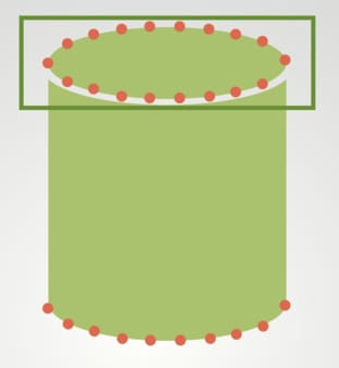
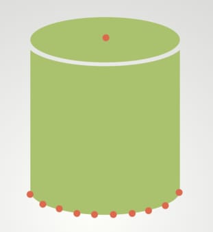
To get the vertices on the upper half of the cylinder we can use an if statement. We will set the x and z components of the position of a vertex, if y component of its position is greater than 0.
v2f vert (appdata v)
{
    v2f o;

    if(v.vertex.y>0){
        v.vertex.x=0;
        v.vertex.z=0;
    }

    o.clipPos=UnityObjectToClipPos(v.vertex);
    return o;
}
Observe that we manipulated the position of the vertex before transforming it into the clip space coordinates.
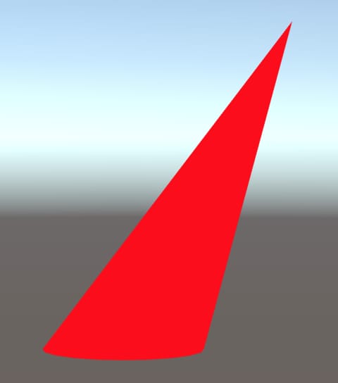
Create a material for this shader, add a cylinder to your scene and assign this new material to your cylinder. You should observe that your cylinder is rendered as a cone.
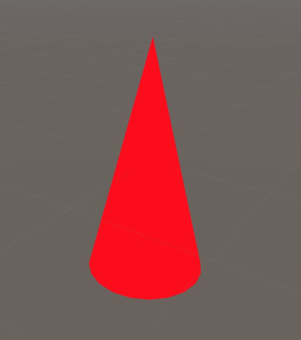
Furthermore, this shader not only transforms cylinders into cones but also transforms cubes into pyramids as seen in the image below.
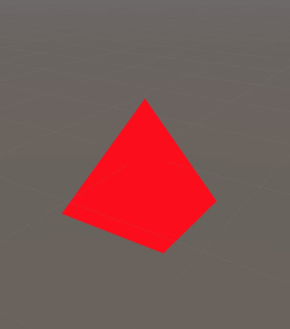
(As mentioned earlier, we have not implemented any lighting model to our shader yet. This is the reason why we could not see the faces of the models.)
Now, let’s add properties that allow us to control the position of the top point.
Add two properties for X and Z Positions in Properties block as follows:
Properties
{
    _MainColor("Main Color", Color)=(1,0,0,1)
    _XPosition("X Position", Float)=0
    _ZPosition("Z Position", Float)=0
}
You should also add two variables that have exact same names with these properties into the CGPROGRAM code block. Now you can control the sharp point from outside of the shader.
This is the complete ConeShader code:
Shader "AdvancedShaderDevelopment/ConeShader"
{
    Properties
    {
        _MainColor("Main Color", Color)=(1,0,0,1)
        _XPosition("X Position", Float)=0
        _ZPosition("Z Position", Float)=0
    }
    SubShader
    {
        Pass
        {
            CGPROGRAM
            #pragma vertex vert
            #pragma fragment frag

            #include "UnityCG.cginc"

            fixed4 _MainColor;
            float _XPosition;
            float _ZPosition;

            struct appdata
            {
                float4 vertex:POSITION;
            };

            struct v2f
            {
                float4 clipPos:SV_POSITION;
            };


            v2f vert (appdata v)
            {
                v2f o;

                if(v.vertex.y>0){
                    v.vertex.x=_XPosition;
                    v.vertex.z=_ZPosition;
                }

                o.clipPos=UnityObjectToClipPos(v.vertex);
                return o;
            }

            fixed4 frag (v2f i) : SV_Target
            {
                return _MainColor;
            }
            ENDCG
        }
    }
}
And this is the result:
Homework
Create a shader that converts a quad to a parallelogram.
Extruding a face
As the second example, we will extrude the top face of the cylinder. Actually this is nearly the same shader as the last example. But this time, we will manipulate the position of the vertex in the y-direction.
Duplicate the ConeShader and change its path to ExtrudeShader.
Replace YPosition property and variable instead of X and Z Positions. Then manipulate the y-components of vertices in if statement.
This is the full code:
Shader "AdvancedShaderDevelopment/ExtrudeShader"
{
    Properties
    {
        _MainColor("Main Color", Color)=(1,0,0,1)
        _YPosition("Y Position", Float)=0
    }
    SubShader
    {
        Pass
        {
            CGPROGRAM
            #pragma vertex vert
            #pragma fragment frag

            #include "UnityCG.cginc"

            fixed4 _MainColor;
            float _YPosition;

            struct appdata
            {
                float4 vertex:POSITION;
            };

            struct v2f
            {
                float4 clipPos:SV_POSITION;
            };

            v2f vert (appdata v)
            {
                v2f o;

                if(v.vertex.y>0){
                    v.vertex.y=_YPosition;
                }

                o.clipPos=UnityObjectToClipPos(v.vertex);
                return o;
            }

            fixed4 frag (v2f i) : SV_Target
            {
                return _MainColor;
            }
            ENDCG
        }
    }
}
And this is the result:
Animating vertices
In this example, let’s add animation to ExtrudeShader.
We use built-in Time variables to create animations in shaders. The list of built-in shader variables can be found here.
In this example, we will manipulate the y-component of the cone sinusoidally.
Since we want to make a fine-tuning, we will use _Time instead of _SinTime.
Duplicate the ExtrudeShader and change its first row as usual.
Remove the YPosition property and variable in CGPROGRAM.
Add an _Amplitude property to properties block. Do not forget to add the same property as a variable to the CGPROGRAM code block.
Properties
{
    _MainColor("Main Color", Color)=(1,0,0,1)
    _Amplitude("Amplitude", Float)=0.5
}
We will manipulate y-component of vertices on the upper half of the cylinder. Therefore, as our previous examples, we manipulate it in if statement block.
We will manipulate the y-component of vertices on the upper half of the cylinder. Therefore, like our previous examples, we manipulate it in the if statement block.
if(v.vertex.y>0){
    v.vertex.y=_Amplitude*sin(_Time.y);
}
According to Unity Shader Documentation, _Time has four components. x is t/20 of the time, y is the t, z is t*2 and w is t*3. y component is suitable for our example.
To calculate the sine of a value, we use sin( ) function in Cg. You can click here to see the Cg documentation of sin( ) function.
Your shader should look like this:
Shader "AdvancedShaderDevelopment/ExtrudingAnimationShader"
{
    Properties
    {
        _MainColor("Main Color", Color)=(1,0,0,1)
        _Amplitude("Amplitude", Float)=0.5
    }
    SubShader
    {
        Pass
        {
            CGPROGRAM
            #pragma vertex vert
            #pragma fragment frag

            #include "UnityCG.cginc"

            fixed4 _MainColor;
            float _Amplitude;

            struct appdata
            {
                float4 vertex:POSITION;
            };

            struct v2f
            {
                float4 clipPos:SV_POSITION;
            };

            v2f vert (appdata v)
            {
                v2f o;

                if(v.vertex.y>0){
                    v.vertex.y=_Amplitude*sin(_Time.y);
                }

                o.clipPos=UnityObjectToClipPos(v.vertex);
                return o;
            }

            fixed4 frag (v2f i) : SV_Target
            {
                return _MainColor;
            }
            ENDCG
        }
    }
}
You should see something like this:
Vertex colors
As mentioned before, vertices can store color data, as well. For instance, assume that we have two vertices that different color values. When these color data is processed by rasterizer(the pipeline stage after vertex shader), color values of fragments between two vertices get interpolated color values. In this example, we will create a color cube.
For this example, BasicShader that we created before is a good starting point. Therefore, start by duplicating existing BasicShader or copy it from here.
We will assign color values to vertices. We will do this in vertex shader and we will assign color values according to positions of vertices.
First of all, change the path of the shader. ColorCubeShaderis a suitable name for this shader.
Shader "AdvancedShaderDevelopment/ColorCubeShader"
Since we want to assign color values to vertices, we have to do it in vertex shader, as mentioned above. Furthermore, we have to declare a variable that the output of the vertex shader will have. Therefore, we have to add a new variable to the v2f struct for color and we also have to indicate the intention that why we declared it.
struct v2f
{
    float4 clipPos: SV_POSITION;
    float4 color: COLOR;
};
In order to reach more information about shader semantics, you can click here to see shader semantics part of Unity’s documentation page.
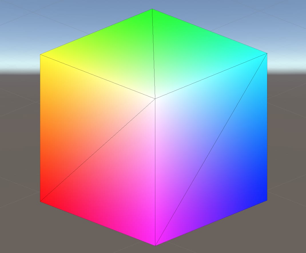
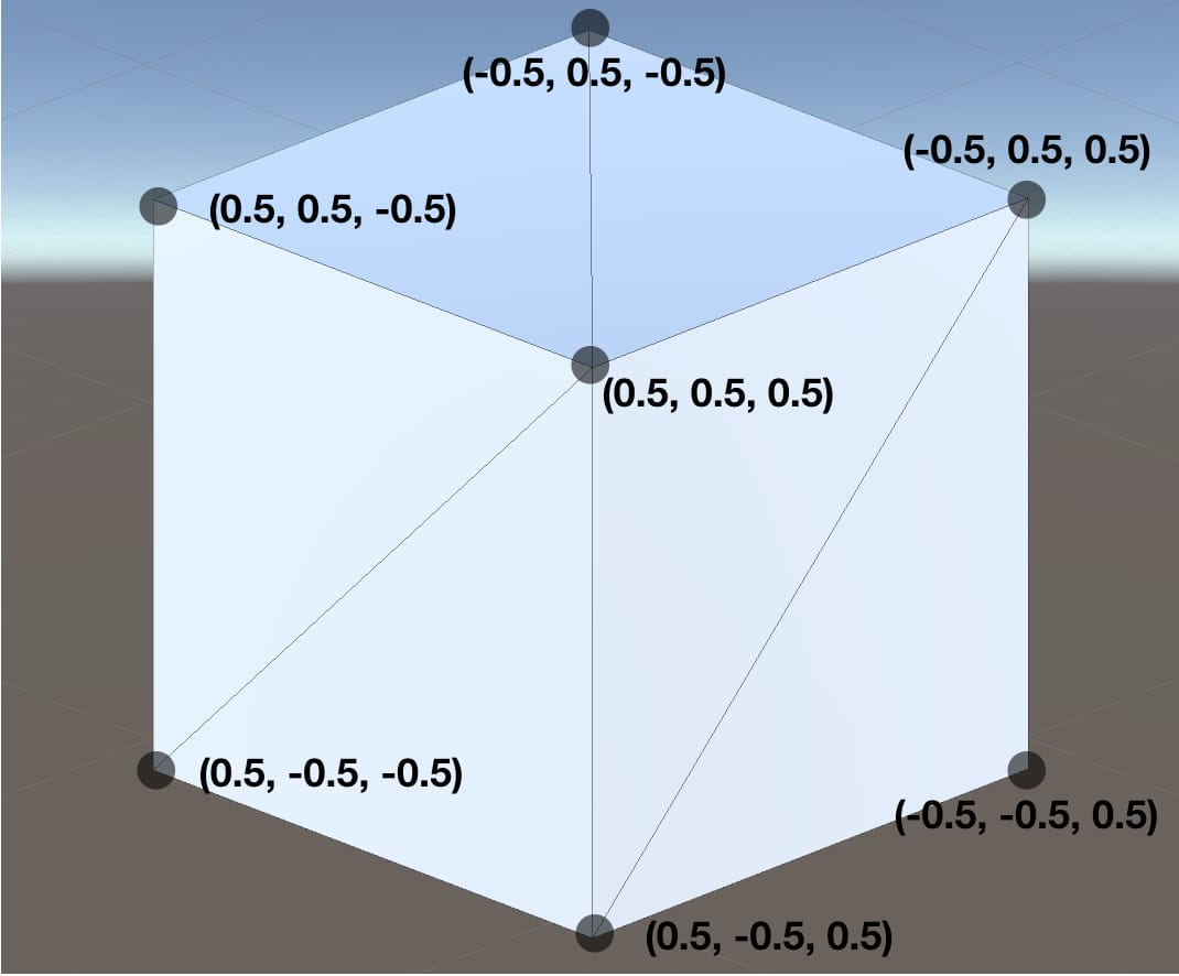
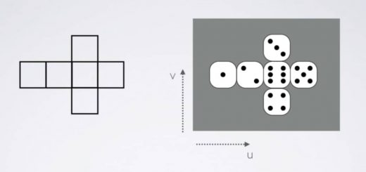
Vertices of a cube and their positions in object space are seen in the image below. We want to assign the position value of each vertex to that vertex as a color value. As you may know, color is represented by 4 numbers(R, G, B and A or, Red, Green, Blue, and Alpha) in computer graphics and a combination of these values give us color.
Modify the vertex shader as following:
v2f vert (appdata v)
{
    v2f o;
    o.color=v.vertex;
    o.clipPos=UnityObjectToClipPos(v.vertex);
    return o;
}
Now, vertices have color values. These values are taken by rasterizer and rasterizer interpolates these values for fragments between vertices. If we want to paint fragments to these interpolated values, we have to do it in fragment shader. We will see the fragment shader in detail in the next tutorial but for now, just change it as the following:
fixed4 frag (v2f i) : SV_Target
{
    return i.color;
}
This is the full shader code:
Shader "AdvancedShaderDevelopment/ColorCubeShader"
{
    Properties
    {
        _MainColor("Main Color", Color)=(1,0,0,1)
    }
    SubShader
    {
        Pass
        {
            CGPROGRAM
            #pragma vertex vert
            #pragma fragment frag

            #include "UnityCG.cginc"

            fixed4 _MainColor;

            struct appdata
            {
                float4 vertex: POSITION;
            };

            struct v2f
            {
                float4 clipPos: SV_POSITION;
                float4 color: COLOR;
            };

            v2f vert (appdata v)
            {
                v2f o;
                o.color=v.vertex;
                o.clipPos=UnityObjectToClipPos(v.vertex);
                return o;
            }

            fixed4 frag (v2f i) : SV_Target
            {
                return i.color;
            }
            ENDCG
        }
    }
}
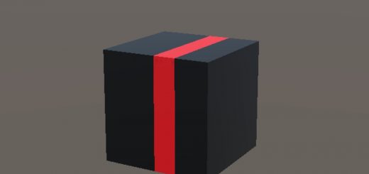
Save this shader, create a material for it and assign it to cube. You should see something like this.
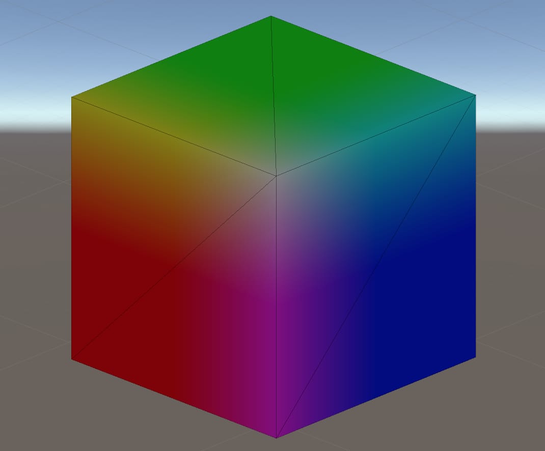
As you can see we have a colorful cube now. But it seems a little bit dark. This is because vertex positions are between -0.5 and 0.5. However, color values should be between 0 and 1. Therefore, we have to remap it to make colors brighter. To do this, add 0.5 to color variable in vertex shader.
v2f vert (appdata v)
{
    v2f o;
    o.color=v.vertex+0.5;
    o.clipPos=UnityObjectToClipPos(v.vertex);
    return o;
}
And this is the result:
In this tutorial, we have learned vertex shader and made several examples in order to reinforce our knowledge. We also mentioned about fragment shader a little bit in the last example. In the next tutorial, we will see fragment shader in detail.

Hey! Thanks for these tutorials 😀 I’m a game artist and I don’t normally code unless I must (because I learnt c# on my own, i.e. I have baaad fundamentals and 0 sense in code architecture)
If I want to get into shaders mostly using Shader Graph, any pointers to how I should be doing it properly? Would it help for me to try and go through the fundamentals of shader programming, or is that wasted time if I’m going to use Shader Graph anyway?
Hey Terri!
Shader Graph is a great tool not only for creating shaders but also for starting shader programming. It is an intuitive way of creating shaders and hence, your progress in shader development could be faster than the traditional shader languages. If you learn to develop shaders using Shader Graph, then it will be much easier to learn Cg, HLSL or GLSL. I highly recommend starting with the Shader Graph.
On the left menu, you can see all the tutorials that I wrote. You can follow them from top to bottom.