Fragment Shader and Manipulating Pixel Colors
In the previous article, we have learned vertex shader and made some examples for it. In this article, we will see fragment shader and we will also work on different examples that will give us intuition about how we use fragment shaders to manipulate pixel colors.
Contents
- What is fragment shader?
- What can we do with fragment shader?
- Fragment color manipulation
- Fragment shader examples
What is fragment shader?
Fragment shader is the graphics pipeline stage that is executed after rasterization. Briefly, a mesh’s data is taken by the GPU and positions of the vertices of the mesh are determined on the screen in vertex shader and rasterizer stages. In rasterizer stage, dots are connected on the screen and thus the shape of the model is projected on the screen. In fragment shader stage, GPU determines the color value that the corresponding pixel will be painted. Fragment shader is the stage that provides shading. It takes the interpolated vertex data which is declared in v2f struct and returns a color value. Like vertex shader, fragment shader also runs simultaneously and you should think as if you are writing the shader for each pixel individually.
What can we do with fragment shader?
As mentioned above, fragment shader returns a color value(generally). This is the only thing which it has to do. This is the only reason for the existence it.
In order to create the illusion of 3-dimension on a 2-dimensional medium like paper you have to shade the objects properly. Without shading, it is impossible to create photorealistic effects. This is the same for computer graphics. If you want to achieve 3-dimensional looking, photorealistic images on a computer or smart phone’s screen, you have to shade it. The required calculations for shading are done in fragment shader and the corresponding pixels are painted to calculated color values. You should implement proper lighting models to achieve physical or psychological effects you would like to achieve in your games.
Fragment color manipulation
In our previous articles, we did not many things about fragment shader. The only thing which we did in the fragment shader was just making it return a plain color. Now, it is time to start working on it.
In BasicShader, we declared a color property to control the _MainColor from outside of the shader in Properties block and returned that color in fragment shader as seen below.
fixed4 frag (v2f i) : SV_Target
{
    return _MainColor;
}
As you may see, fragment function takes a parameter that is in the v2f struct and returns a color value in fixed4 type(As mentioned before, there are three floating-point number types in Cg. They are fixed, half and float). Actually, frag function does not have to take a parameter here, since we do not use it, but fragment shader generally is not so simple and thus we write it like this all the time. SV_Target keyword states the intention of the returning value. It is called as shader semantics. In previous articles, we have mentioned it. For now, I suggest you do not worry about it.
Fragment Shader Examples
Drawing a line on an object
In this example, we will draw a vertical line on an object. Moreover, we will add properties in which we will be able to control the line color, line position, and line width.
First, create a shader and copy and paste the BasicShader that we have written before. Change the shader name to LineShader and also do not forget to change the path of the shader which is in the first row.
Shader "AdvancedShaderDevelopment/LineShader"
We will make modifications in v2f struct, vertex shader, and fragment shader.
For now, forget the line and assume that you only want to paint the right side of the object to a controllable color. To do this, first, we need to determine if a fragment is located on the right of the object or on the left of the object. Since we determine the color of the pixel in fragment shader, we have to pass object space coordinates to fragment shader. In order to pass object space coordinates to fragment shader, we include a variable to v2f struct which will store fragment coordinates in object space(Remember that rasterizer interpolates vertex data and thus we get fragment coordinates).
struct v2f
{
    float4 clipPos:SV_POSITION;
    float4 objectPos:TEXCOORD0;
};
We use a variable that has TEXCOORD semantic to store position or texture coordinate values in output of vertex shader and input of fragment shader (You can check Unity Shader Semantics Documentation).
Now, we have to assign vertex positions of the object to objectPos variable. We have to do this in vertex shader. Thus, this data will be processed in rasterizer and we will be able to pass the positions of fragments in object space to fragment shader.
v2f vert (appdata v)
{
    v2f o;
    o.clipPos=UnityObjectToClipPos(v.vertex);
    o.objectPos=v.vertex;
    return o;
}
Finally, we have to check if the x component of the position of the fragment(remember, we think as if we are writing shaders only for one pixel) is greater than 0. If so we will return the _MainColor value otherwise black value.
fixed4 frag (v2f i) : SV_Target
{
    fixed4 col;

    if(i.objectPos.x>0){
        col=_MainColor;
    }
    else{
        col=fixed4(0,0,0,1);
    }
    return col;
}
This is the complete shader code up to now.
Shader "AdvancedShaderDevelopment/LineShader"
{
    Properties
    {
        _MainColor("Main Color", Color)=(1,0,0,1)
    }
    SubShader
    {
        Pass
        {
            CGPROGRAM
            #pragma vertex vert
            #pragma fragment frag

            #include "UnityCG.cginc"

            fixed4 _MainColor;

            struct appdata
            {
                float4 vertex:POSITION;
            };

            struct v2f
            {
                float4 clipPos:SV_POSITION;
                float4 objectPos:TEXCOORD0;
            };

            v2f vert (appdata v)
            {
                v2f o;
                o.clipPos=UnityObjectToClipPos(v.vertex);
                o.objectPos=v.vertex;
                return o;
            }

            fixed4 frag (v2f i) : SV_Target
            {
                fixed4 col;

                if(i.objectPos.x>0){
                    col=_MainColor;
                }else{
                    col=fixed4(0,0,0,1);
                }

                return col;

            }
            ENDCG
        }
    }
}
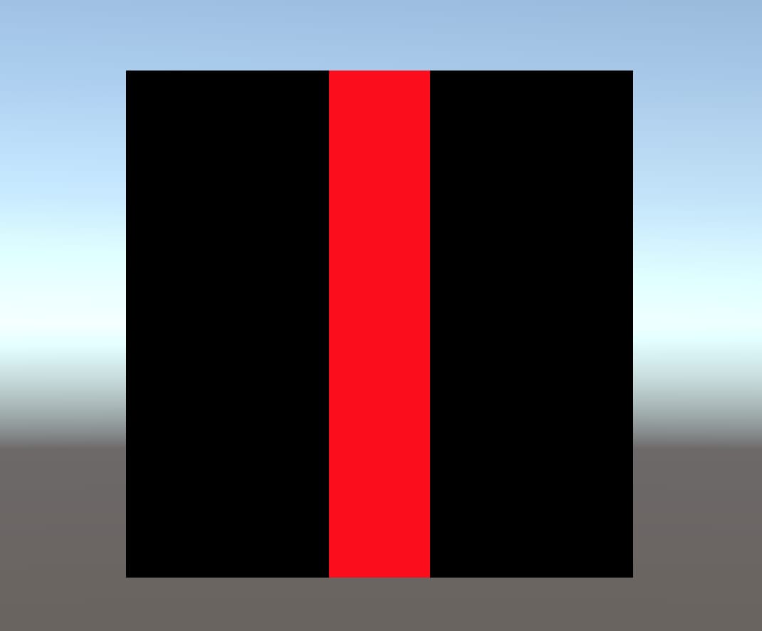
This is the result of this shader on a quad:
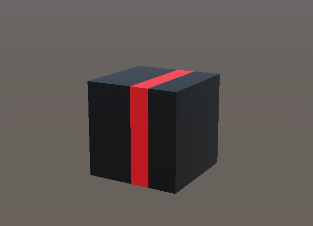
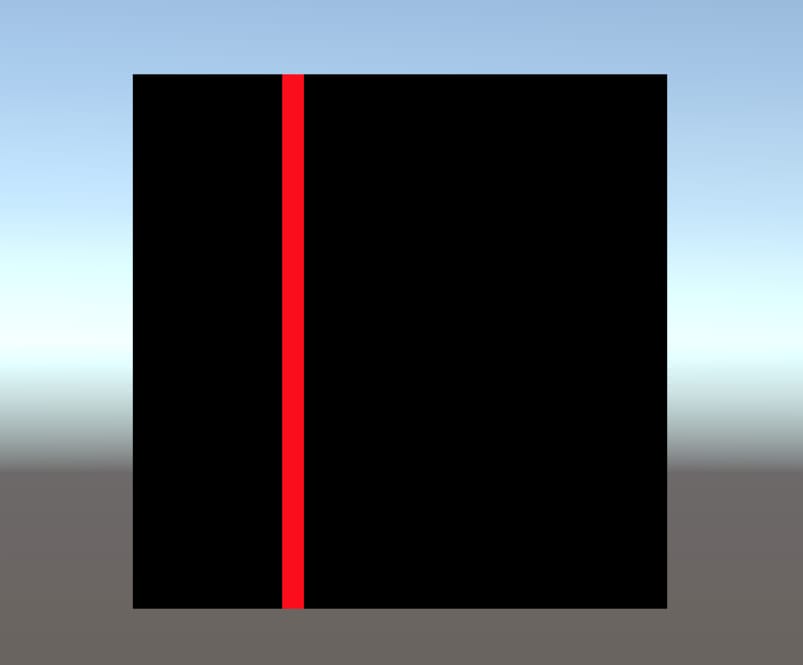
Let’s go a step further and add properties in order to control the line width and line position.
Shader "AdvancedShaderDevelopment/LineShader"
{
    Properties
    {
        _MainColor("Main Color", Color)=(1,0,0,1)
        _LineWidth("Line Width", Float)=0.2
        _XPosition("X Position of the Line", Float)=0
    }
    SubShader
    {
        Pass
        {
            CGPROGRAM
            #pragma vertex vert
            #pragma fragment frag

            #include "UnityCG.cginc"

            fixed4 _MainColor;
            float _LineWidth;
            float _XPosition;

            struct appdata
            {
                float4 vertex:POSITION;
            };

            struct v2f
            {
                float4 clipPos:SV_POSITION;
                float4 objectPos:TEXCOORD0;
            };

            v2f vert (appdata v)
            {
                v2f o;
                o.clipPos=UnityObjectToClipPos(v.vertex);
                o.objectPos=v.vertex;
                return o;
            }

            fixed4 frag (v2f i) : SV_Target
            {
                fixed4 col;

                if(i.objectPos.x>_XPosition-_LineWidth/2 && i.objectPos.x<_XPosition+_LineWidth/2)
                {
                    col=_MainColor;
                }else{
                    col=fixed4(0,0,0,1);
                }

                return col;

            }
            ENDCG
        }
    }
}
Homework 1
Draw a horizontal line. You should be able to control the line color, line width, and line position.
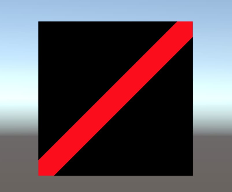
Homework 2
Draw a diagonal line from the bottom left corner to the top right corner like the image below.
Drawing a Circle
In this example, we will draw a circle on an object. This is similar to the shader which we created in the last example.
I will start from the BasicShader and make modifications in v2f struct and vertex shader like the previous example.
struct v2f
{
    float4 clipPos:SV_POSITION;
    float4 objectPos:TEXCOORD0;
};

v2f vert (appdata v)
{
    v2f o;
    o.clipPos=UnityObjectToClipPos(v.vertex);
    o.objectPos=v.vertex;
    return o;
}
Mathematical equation of a circle is given by the following:
\( x^2+y^2=r^2\)
We will calculate the sum of the squares of the x and y components of the fragment’s position, then compare it with the square of a certain radius value.
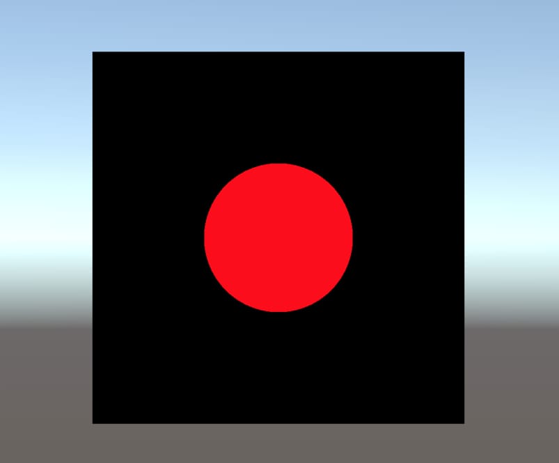
The following shader gives us a circle, that is located at the center of the object, which has a radius of 0.2 units.
Shader "AdvancedShaderDevelopment/CircleShader"
{
    Properties
    {
        _MainColor("Main Color", Color)=(1,0,0,1)

    }
    SubShader
    {
        Pass
        {
            CGPROGRAM
            #pragma vertex vert
            #pragma fragment frag

            #include "UnityCG.cginc"

            fixed4 _MainColor;

            struct appdata
            {
                float4 vertex:POSITION;
            };

            struct v2f
            {
                float4 clipPos:SV_POSITION;
                float4 objectPos:TEXCOORD0;
            };


            v2f vert (appdata v)
            {
                v2f o;
                o.clipPos=UnityObjectToClipPos(v.vertex);
                o.objectPos=v.vertex;
                return o;
            }

            fixed4 frag (v2f i) : SV_Target
            {
                fixed4 col;
                float r_sq=i.objectPos.x*i.objectPos.x+i.objectPos.y*i.objectPos.y;

                if(r_sq<0.2*0.2){
                    col=_MainColor;
                }else{
                    col=fixed4(0,0,0,1);
                }

                return col;

            }
            ENDCG
        }
    }
}
Even though there is a function(pow( )) that returns the powers of the numbers, we multiplied the numbers with themselves to find squares since this is more performance-friendly.
This is the result of this shader.
Homework 3
Modify the CircleShader such that you can control the color, radius, and position of the circle from the Unity editor.
Creating a Gradient
In this example, we will create a gradient on the object according to y component of the fragment position.
This is similar to what we created before but this time we will return a color value by multiplying y component of the position of the fragment with the _MainColor.
Shader "AdvancedShaderDevelopment/GradientShader"
{
    Properties
    {
        _MainColor("Main Color", Color)=(1,0,0,1)

    }
    SubShader
    {
        Pass
        {
            CGPROGRAM
            #pragma vertex vert
            #pragma fragment frag

            #include "UnityCG.cginc"

            fixed4 _MainColor;

            struct appdata
            {
                float4 vertex:POSITION;
            };

            struct v2f
            {
                float4 clipPos:SV_POSITION;
                float4 objectPos:TEXCOORD0;
            };

            v2f vert (appdata v)
            {
                v2f o;
                o.clipPos=UnityObjectToClipPos(v.vertex);
                o.objectPos=v.vertex;
                return o;
            }

            fixed4 frag (v2f i) : SV_Target
            {

                return _MainColor*i.objectPos.y;

            }
            ENDCG
        }
    }
}
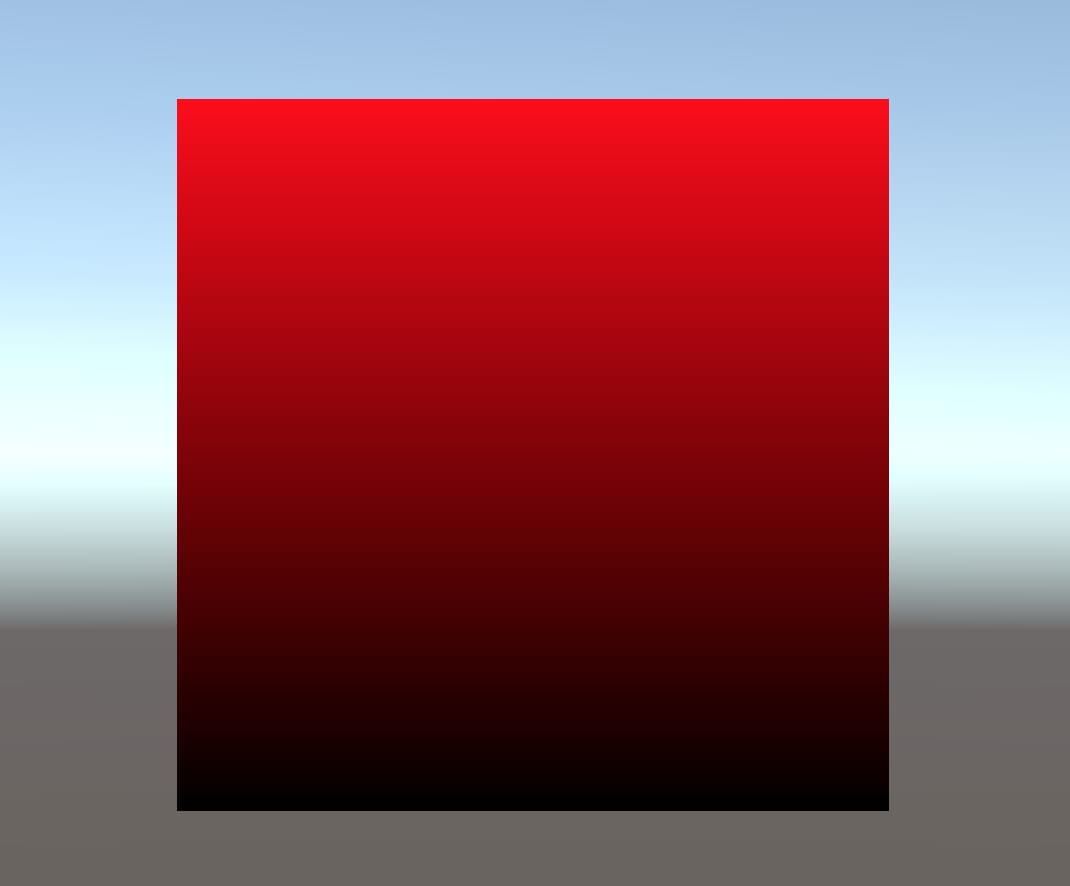
This is the result of this shader:
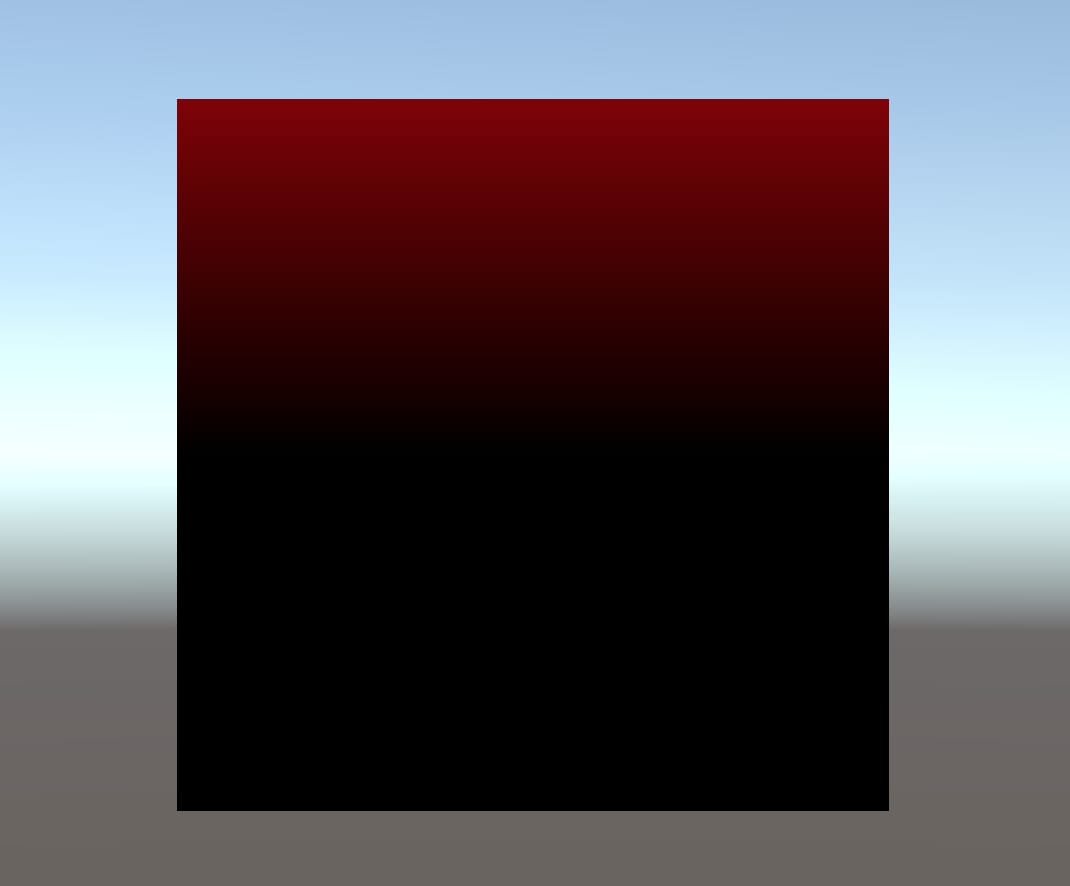
It seems dark. The reason for this is the following: Color values need to be between 0 and 1. However, object space coordinates of this object between -0.5 and 0.5. If we add 0.5 units to the y component of the position of the fragment, we will get a completely red color at the top of the object and black color at the bottom.
Drawing a Vertical Line according to World Space
Sometimes, we have to manipulate pixel colors or vertex positions in world space coordinates. And when we want to implement lighting models, we calculate lighting in world space coordinates since lights are located in world space. Therefore, it is crucial to know to work in world space coordinates. In this example, we will draw a vertical line on an object according to world space coordinates.
In the article “Coordinate Spaces and Transformations Between Them“, we have seen how we can transform coordinates in a coordinate space to another coordinate space. For instance, in all of our shaders we transformed object space coordinates to clip space coordinates in vertex shader using UnityObjectToClipPos( ) built-in function. However, there are no built-in functions for every coordinate transformation. In these cases, we have to transform coordinates by multiplying them with transformation matrices.
As mentioned at that post, the transformation matrix that transforms coordinates from object space coordinates to world space coordinates is called model matrix and it is given by unity_ObjectToWorld. And also we perform multiplication operation using mul( ) function.
The following shader draws a vertical line on an object according to world space positions.
Shader "AdvancedShaderDevelopment/LineShader_w"
{
    Properties
    {
        _MainColor("Main Color", Color)=(1,0,0,1)
        _LineWidth("Line Width", Float)=0.2
        _XPosition("X Position of the Line", Float)=0
    }
    SubShader
    {
        Pass
        {
            CGPROGRAM
            #pragma vertex vert
            #pragma fragment frag

            #include "UnityCG.cginc"

            fixed4 _MainColor;
            float _LineWidth;
            float _XPosition;

            struct appdata
            {
                float4 vertex:POSITION;
            };

            struct v2f
            {
                float4 clipPos:SV_POSITION;
                float4 worldPos:TEXCOORD0;
            };

            v2f vert (appdata v)
            {
                v2f o;
                o.clipPos=UnityObjectToClipPos(v.vertex);
                o.worldPos=mul(unity_ObjectToWorld, v.vertex);
                return o;
            }

            fixed4 frag (v2f i) : SV_Target
            {
                fixed4 col;

                if(i.worldPos.x>_XPosition-_LineWidth/2 && i.worldPos.x<_XPosition+_LineWidth/2){
                    col=_MainColor;
                }else{
                    col=fixed4(0,0,0,1);
                }

                return col;

            }
            ENDCG
        }
    }
}
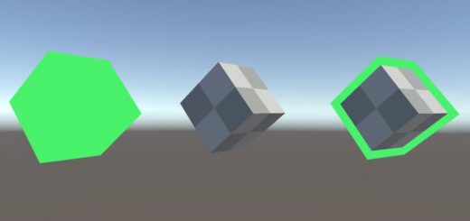
The first gif shows a line which is drawn in world space. And the second one is the line which is drawn in the object space.