Creating a Basic Shader and Its Anatomy
In this article, we will start to write our first shader by explaining every step. This shader will be a basis for future shaders. We will also investigate the anatomy of shaders.
Contents
- Creating the first shader
- Anatomy of a shader
- A brief introduction to the graphics rendering pipeline
- CGInclude files
- How does BasicShader work?
- Properties
Creating the first shader
Warning: In these tutorial series, we will use the default render pipeline of Unity3D. URP(LWRP) and HDRP have some restrictions and therefore you may not obtain the same results if you use them. After you learn how to develop shaders, you will be able to create shaders also using these new pipelines. But for now, I advise you to follow the steps here.
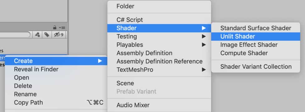
Let’s start by creating a shader. To do this, right-click on the “Project Window”. Then Create-Shader and choose Unlit Shader. Change its name to “BasicShader”.
Double click to open it, remove all the existing code and replace with the following code:
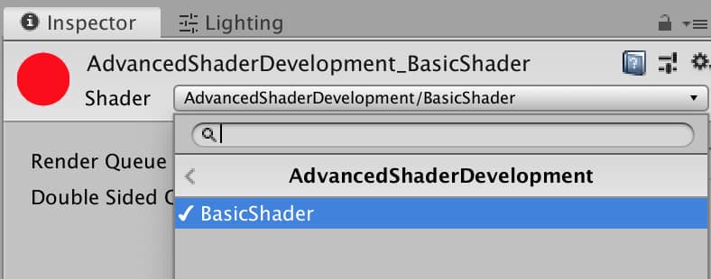
Shader "AdvancedShaderDevelopment/BasicShader"
{
    Properties
    {

    }
    SubShader
    {
        Pass
        {
            CGPROGRAM
            #pragma vertex vert
            #pragma fragment frag

            #include "UnityCG.cginc"

            struct appdata
            {
                float4 vertex:POSITION;
            };

            struct v2f
            {
                float4 clipPos:SV_POSITION;
            };


            v2f vert (appdata v)
            {
                v2f o;
                o.clipPos=UnityObjectToClipPos(v.vertex);
                return o;
            }

            fixed4 frag (v2f i) : SV_Target
            {
                return fixed4(1,0,0,1);
            }
            ENDCG
        }
    }
}
Anatomy of a shader
In the code above, there are two different languages. The first one is ShaderLab and the second one is Cg. Everything between the keywords CGPROGRAM and ENDCG is written in Cg. And everything outside of these keywords is written in ShaderLab.
The purpose of the ShaderLab is to connect Unity3D engine with the actual shader code.
The main body of the shader is in Cg language.
At the top of the code, we declare the path of the shader in material inspector.
Shader "AdvancedShaderDevelopment/BasicShader"
In Properties block, we declare the variables which we want to access from outside of the shader. We will talk about it in detail below.
Properties
{

}
If we want to target different graphics apis in our shader, we have to write a different Subshader for each of them.
SubShader
{

}
For instance, assume that you are targeting Vulkan API. But not all hardware support it. If you want to support another graphics API like OpenGL or Metal, then you need to add another subshader. Nevertheless, for now, you should not worry about it because all of the shaders, which we will write, will work fine for all graphics APIs and hardware.
The aim of the Pass is to draw and shade something. If you want to draw two images from one object, you have to write two Pass. If you have ever looked Statistics tab in Game view before, you have probably seen the term SetPass call. This term refers to this Pass. If you draw two images from one model, SetPass call will be two. We will see this later in detail.
Pass
{

}
Now it is time to explain the main part. As I mentioned above, we write the actual shader code between CGPROGRAM and ENDCG. In the shader code, which you copied above, there are two functions and two structs. In addition, there are two pragma directives.
Vertex and fragment functions are declared using pragma directives. In this shader, our vertex function’s name is vert and fragment function’s name is frag.
#pragma vertex vert
#pragma fragment frag
And these are the vertex function and fragment function:
v2f vert (appdata v)
{

}

fixed4 frag (v2f i) : SV_Target
{

}
In C-like languages, there is a data container structure that is declared using struct keyword.
struct appdata
{

};

struct v2f
{

};
In our shader, appdata and v2f are two different structs. We declare variables that we want to be processed in vertex and fragment functions in these structs. Names of them are not fixed and you can give any name to them.
In Cg, there are three different floating-point number datatypes. These are fixed, half and float. We also use them for vector data types. For instance, fixed4 indicates a 4-dimensional, fixed valued vector.
A brief introduction to graphics rendering pipeline
At this point, it is a good idea to talk about the graphics rendering pipeline. This is not a complete discussion about it because it is not easy to understand the whole pipeline at first. Therefore, we will divide it into small chunks and expand when it is required.
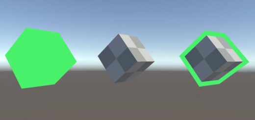
A mesh is nothing but only a list of mathematical coordinates of vertices. When you export a 3D model from Maya or Blender or any other 3D modeling software, actually you export a list of positions of vertices.
When the CPU wants to draw this object on the screen, it makes a drawcall.
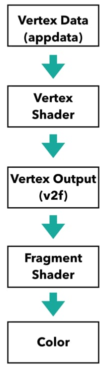
Thus, vertex data pass to the vertex shader. We tell which vertex data will be processed by vertex shader in appdata struct. (Even though a vertex can have other data like color or normal vector, for now, we only deal with position.) Vertex function gives an output. We also declare which data will be out from vertex shader in v2f struct.
We will also talk about it later but let me tell you what vertex shader does with vertex data. It transforms object space coordinates to clip space coordinates. If you have not understood what I am talking about, do not worry, just keep reading. You will understand better in the future. The only thing which you have to understand at the moment is that we declare what the input and output of the vertex shader in appdata and v2f structs, and vertex shader locate those vertices to the desired positions.
After vertex shader makes required calculations, this data pass to fragment shader(actually there are some other stages between vertex and fragment shaders, but we will not talk about them yet). The data, which is declared in v2f struct, is the input of the fragment function at the same time. Fragment function takes this data and after making the required calculations color the pixels. Generally, all lighting calculations are made in this stage.
There are two more things that you have to know here. The first one is the following: All this graphics pipeline is a parallel operation. In other words, vertex shader runs for each vertex and fragment shader runs for each fragment, simultaneously. You should think that you are writing the shader for only one vertex and pixel. And in runtime, they are executed independently for each vertex and fragment.
The second important point is that shaders run only during one frame time. In every frame, they are executed again and they forget what they did at the last frame. Shaders do not have a memory. You cannot reach what they rendered at the last moment.
These are very important points that we will return again. I am aware that these is very abstract but do not worry about it now.
CGInclude files
In Cg, there are several built-in functions. We use them in future shaders. In addition to them, there are also external libraries for Unity. If you want to import an external library, you can do this as the following:
#include "UnityCG.cginc"
This is the library which includes UnityCG helper functions. In order to see the list of these functions click here. Also, you can create your own libraries and import them to use in your shaders. We will see how to do this in future articles.
How does BasicShader work?
Let’s review everything that we mentioned above by explaining how the basic shader works.
Assume that we have a mesh and we want it to be rendered on the screen with a red color. This can be any mesh. It could be exported from Blender, it could be bought from the asset store or it could be generated procedurally. For this example, let’s use one of Unity’s primitive meshes. The mesh consists of mathematical coordinates in 3D world which are located relative to mesh’s pivot point.
Since Since we want to render this mesh on the screen, first we have to calculate the positions of the vertices on the screen. In other words, vertex shader will take positions of vertices of the object and locate them on the screen. This means that in appdata struct we have to declare object space positions because we want them to be processed by the vertex shader.
struct appdata
{
    float4 vertex:POSITION;
};
POSITION keyword is called system semantics and we use it to declare our intention to use the variable. As you may notice, a 4-dimensional vector can represent several other values like color. Since the variable vertex is declared to store a position, we specify it like this.
The output of the vertex shader will be the positions of the vertices in clip space(do not worry about clip space, in the next article we will talk about it in detail). This means that we have to declare output positions in v2f struct.
struct v2f
{
    float4 clipPos:SV_POSITION;
};
Since we determined the input and output data of vertex shader, we can explain the vertex shader.
v2f vert (appdata v)
{
    v2f o;
    o.clipPos=UnityObjectToClipPos(v.vertex);
    return o;
}
Vertex shader takes a variable that has a data type appdata and gives an output in the datatype v2f. Therefore, we declared a variable o that is in data type v2f. Then we calculated the positions of the vertices in clip space using UnityObjectToClipPos() function. This function is a Unity CG helper function that we already included. In the next article, while we are talking about coordinate spaces, we will talk about this function also.
After the vertex positions are determined, now it is time to color the pixels that are inside the area between vertices. We determine the pixel color in the fragment shader. For instance, the following fragment shader paints pixels to red color.
fixed4 frag (v2f i) : SV_Target
{
    return fixed4(1,0,0,1);
}
In fragment function, we return a color as a 4-dimensional vector. The first three numbers represent Red(R), Green(G) and Blue(B) channels and the last one is the Alpha(A) channel.
Now, let’s check what we get.
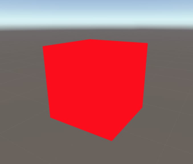
Save this shader and create a material for it. You should select this shader for your material. Create a primitive Unity mesh like Cube. And assign the new material to the object. You should see something like this:
As you see we have a lovely, red cube. But as you notice, we cannot see surfaces of the cube. This is because there is no lighting model implemented in our shader. We will implement lighting models in later chapters.
Properties
We can control shader properties from outside of the shaders. To do this, we add the variables, that we want to control, to the Properties block. As an example let’s control the color of the object from the material inspector.
To do this add a color property like the following.
Properties
{
    _MainColor("Main Color", Color)=(1,0,0,1)
}
In order to connect this property with the Cg code block, we have to add a variable that has exactly the same name as this property. And we have to return this variable in the fragment shader. Our final shader should look like this:
Shader "AdvancedShaderDevelopment/BasicShader"
{
    Properties
    {
        _MainColor("Main Color", Color)=(1,0,0,1)
    }
    SubShader
    {
        Pass
        {
            CGPROGRAM
            #pragma vertex vert
            #pragma fragment frag

            #include "UnityCG.cginc"

            fixed4 _MainColor;

            struct appdata
            {
                float4 vertex:POSITION;
            };

            struct v2f
            {
                float4 clipPos:SV_POSITION;
            };


            v2f vert (appdata v)
            {
                v2f o;
                o.clipPos=UnityObjectToClipPos(v.vertex);
                return o;
            }

            fixed4 frag (v2f i) : SV_Target
            {
                return _MainColor;
            }
            ENDCG
        }
    }
}
Now we can control the color of the cube from material editor.
This is the end of the article. In the next one, we will learn about coordinate spaces and transformation between them. We will also complete some of the gaps in the graphics rendering pipeline.