The Big Shader Graph Tutorial: Second Part
Edit: This article is part of our tutorial series in Shader Graph. We have several step by step shader graph tutorials. If you would like to see the full list of our shader graph tutorials, you can click here.

This is the second part of the Big Shader Graph Tutorial. In the first part, we learned how shaders work, how we can set up the project for Shader Graph and what the PBR Master Node is. Finally, we created a basic shader.
In this part of the tutorial, we will use other ports of the PBR Master Node and also learn several other nodes which we will use to create more complex shaders.
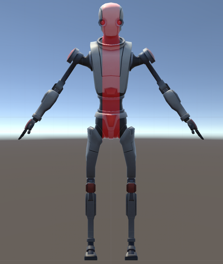
You can use any model or textures to follow these tutorials but we will use Robot Kyle for the later sections from the Unity Asset Store and you may use it if you would like.
Drawing A Line using Shader Graph
In the first example of this part of the tutorial, we will draw a vertical line on an object. This is still not a very complex shader but it will be very informative especially for those who are not familiar with the parallel nature of the shaders.
We want to modify each pixel color according to their coordinates. Therefore we have to compare the position of each pixel with two values to determine if it is between them. Imagine that our program is for a pixel that belongs to an object.
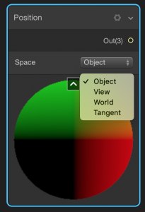
First, add Position Node. To add a Position Node, right-click then choose Create Node. Type “Position” on the Menu and press enter. This will create a Position Node. From the dropdown menu, select “Object Space”. Position Node gives us the position of any individual pixel.
The second step is to obtain only x-component of the position of the pixel. Since we want to drive a vertical line, we need x-component. To do this we have to add a Split Node.
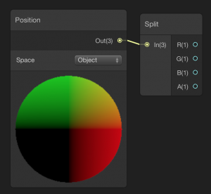
Split Node has one input and four output ports. The input port takes a vector input up to 4-dimensions and gives output for each component. If we need to get the x value from a vector, we use port R of the split node. Likewise, for y-component port G, for z-component port B, and for w-component port A is used. Connect the Position Node to the Split Node.
Now it is time to compare the position of the pixel with a value. This something like if-statement. To compare two values, we have to add Comparison Node. Comparison Node takes two values, compare them and gives a True or False value as an output. We need to convert this boolean value to a number -0 or 1-. To do this, we use a Branch Node.
Add a Comparision Node and a Branch Node. Configure them as the following image.
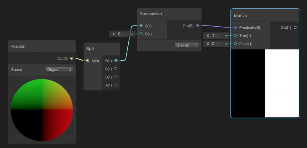
Therefore, we get the x-component of the pixel and compare it with 0. If it is greater than zero, then we have 1 and smaller then zero, we have 0.
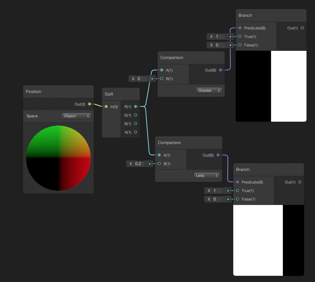
This was the left border of the line. Do the same steps for the right border of the line. This time you should check if the x-component of the pixel is smaller than a value that is greater than zero (In our example it is 0.2). You should reach something like this:
Now, let’s connect these two branches using a Multiply Node.
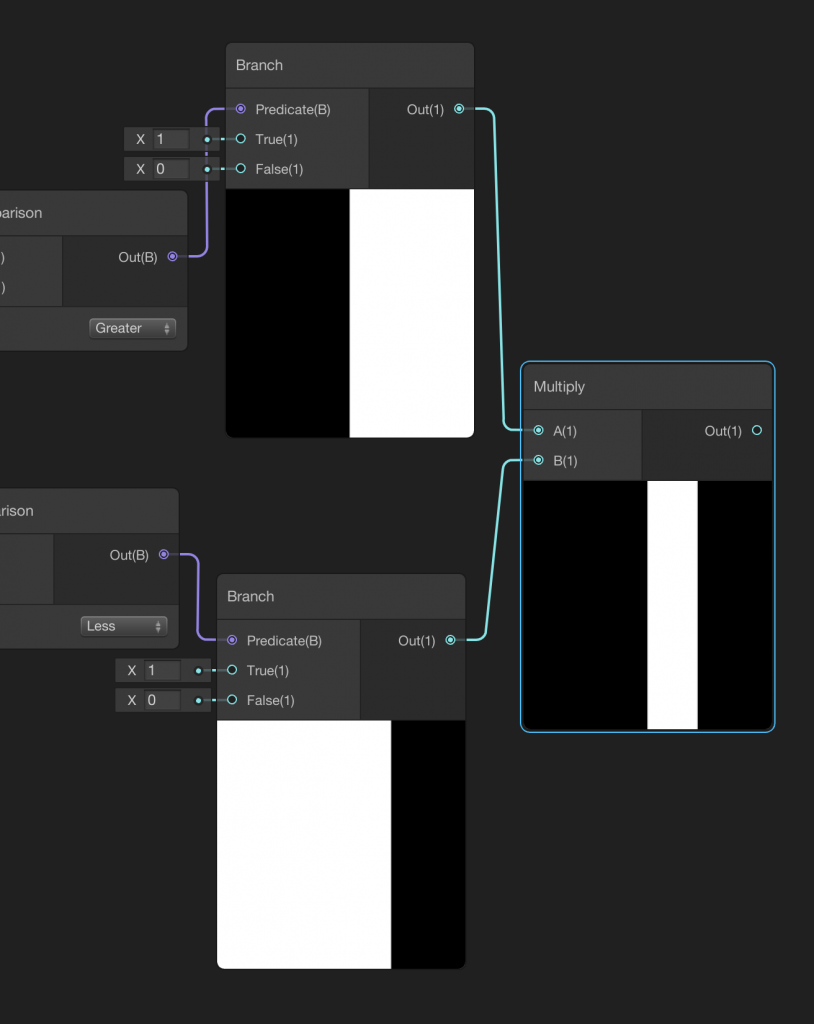
We have already created a vertical line. If we connect the output of the Multiply Node to Albedo port of the PBR Master Node, we will see a white line on a black object. But before that, let’s go step further and add Color Property to control the color of the shader. In the previous tutorial, we already learned how to add a property.
Add a Color Property and multiply it with the first Multiply Node.
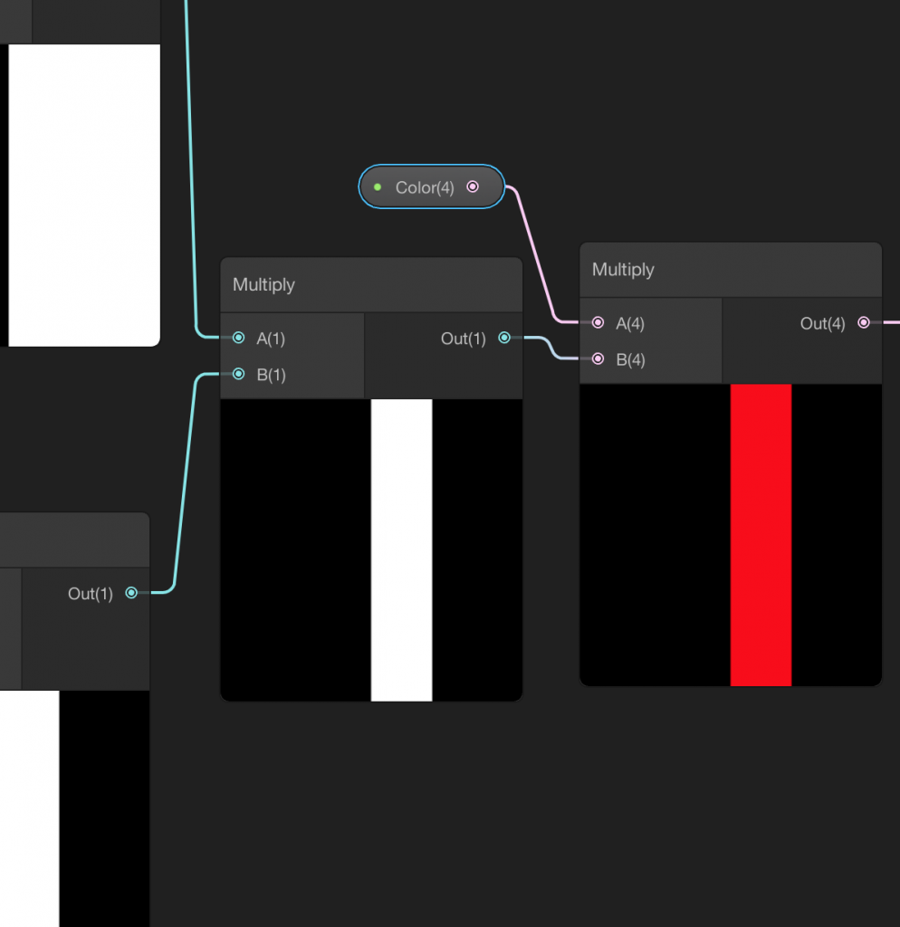
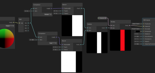
Finally, connect the output of the second Multiply Node to the Albedo Port of the PBR Node. Final Shader Graph should look like this.
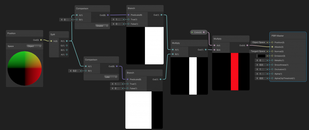
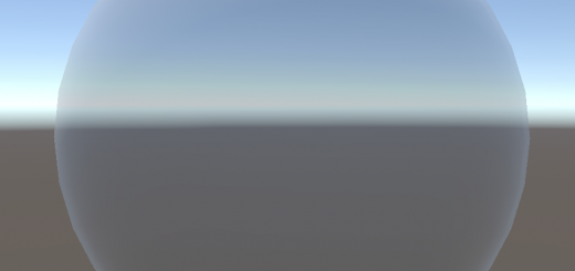
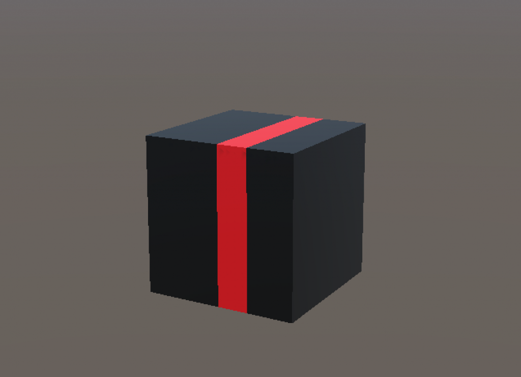
This is what we get when we attach this shader to an object.
Let’s continue and add two more properties for line width and line position. These must be vector1 type. We will compare the position of the pixel with the line position plus and minus half of the line width. Modify the Shader Graph as follows:
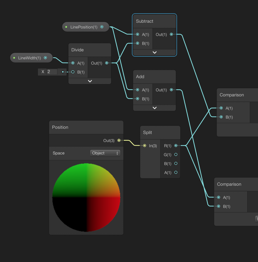
Now we can control the line color, line width and line position.
Texture Mapping in Shader Graph
As a second example in this tutorial, we will learn texture mapping. It is also known as UV mapping. Texture mapping is a technique that is necessary to achieve photorealism. By using this technique we cover an object with a texture.
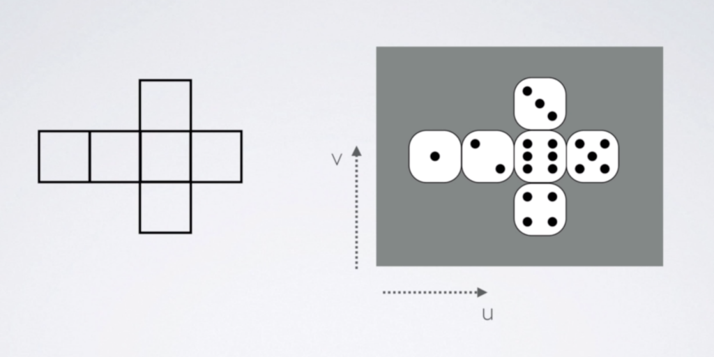
For instance, you see the layout of a cube on the left side and a texture on the right. When we want to cover the object with a texture, we map each point of the layout to each point of the texture.
Let’s create a new shader using shader graph.
First, we need to add a Texture2D property. Therefore, we can add a texture from the material inspector. Then we have to map this texture to the 3D mesh. To do this, we need to add a Sample Texture 2D Node. Hence, we determine the color of the pixel (remember, we imagine that we are writing this program for only one pixel). Then connect the output of the Sample Texture 2D Node to Albedo port of the PBR Master Node.
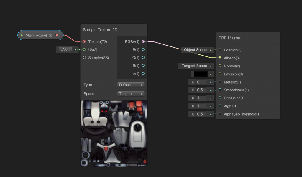
The shader will look like this:
Normal Mapping in Shader Graph
Now it is time to increase the photorealism of our shader. A must method to increase photorealism is normal mapping. Look at the image below.

A real object may have several cracks and some periodic or non-periodic patterns. To simulate these cracks or patterns we can shape the mesh. But this method is very expensive, especially for real-time rendering. A widespread and cost-effective method is to use normal mapping. By using normal mapping, we manipulate surface normals on the surface of the object and change the path of the reflected light rays to simulate roughness.
Adding a normal map to our shader is similar to adding the main texture. The only difference is to change the type of texture in the Sample Texture 2D Node. You should also set the mode to Bump in the NormalTexture property.
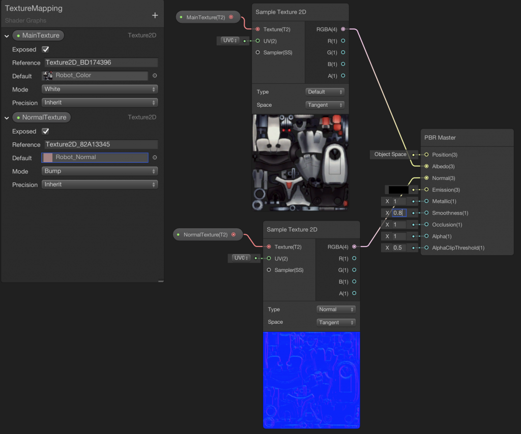
When you set the Metallic value to 1 and Smoothness value to 0.8 in the PBR Master Node, you should see the following results.

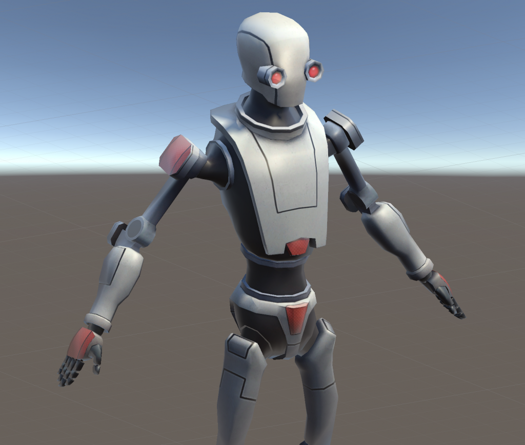
You see the difference between surfaces which a normal map attached(image on the left) or not(image on the right).
Combining What We Have Learned In This Part
Now it is time to combine the knowledge which we have learned in this tutorial. In this section, our goal is to draw a vertical line on Robot Kyle. The vertical line will be seen with the texture of the Robot Kyle. Before to continue please try to do it by yourself.
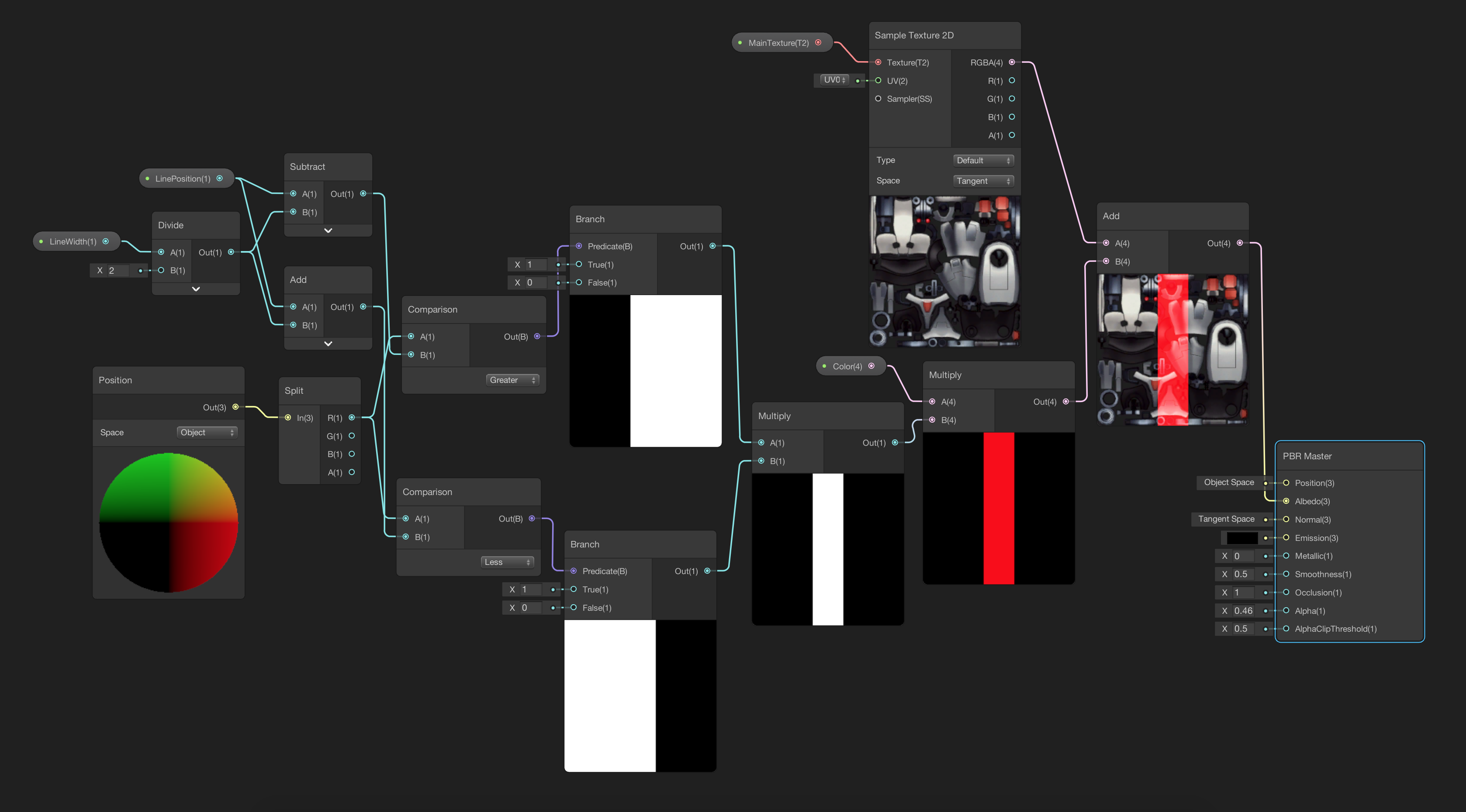
This is quite easy. The only thing which we have to do is to add a main texture to the vertical line shader and sum the texture branch and line branch before connecting them to the PBR Master Node.
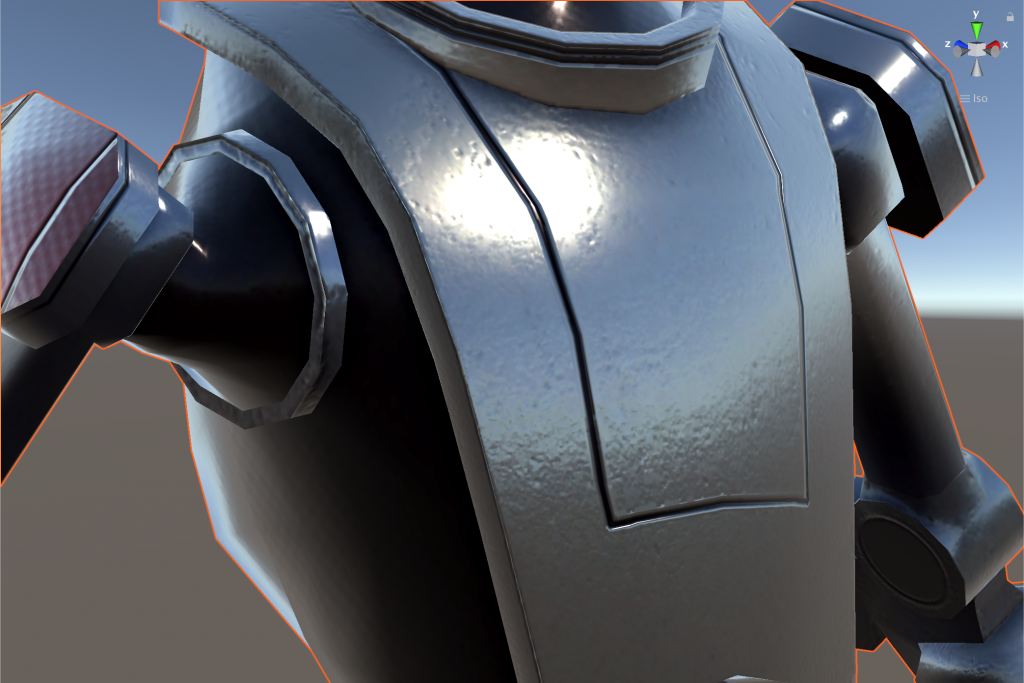
Let’s look at what we get.
Oops! This is not what we wait for. We used x-positions to draw the line but our shader has drawn it horizontal. Why?
This is because we work in object space and positions in object space do not have to be in the same directions in world space. This means that Robot Kyle is designed so that its x-positions are from feet to head. Therefore, if we want to draw a line from head to feet, then we have to manipulate pixel colors according to z-positions as follows.
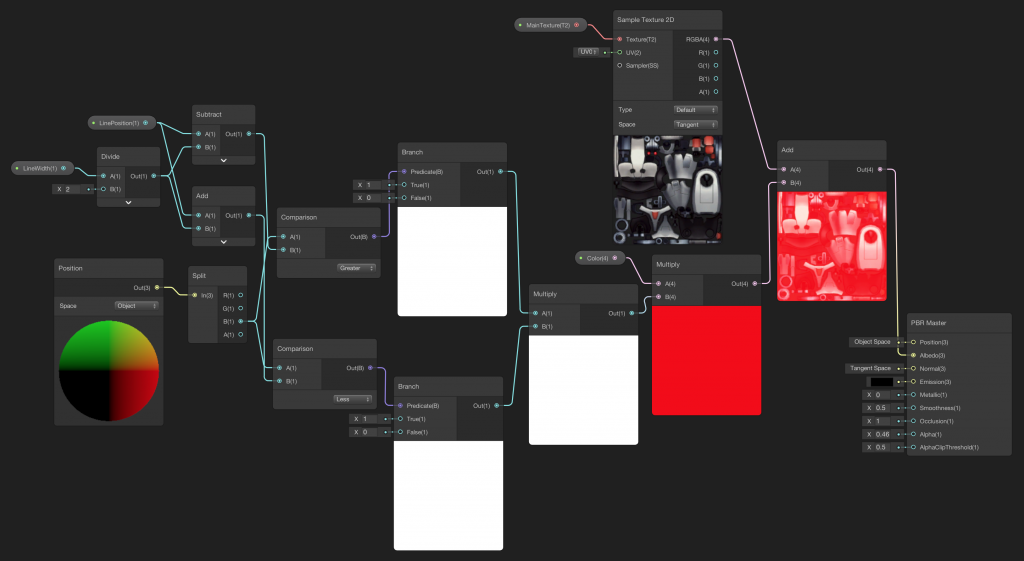
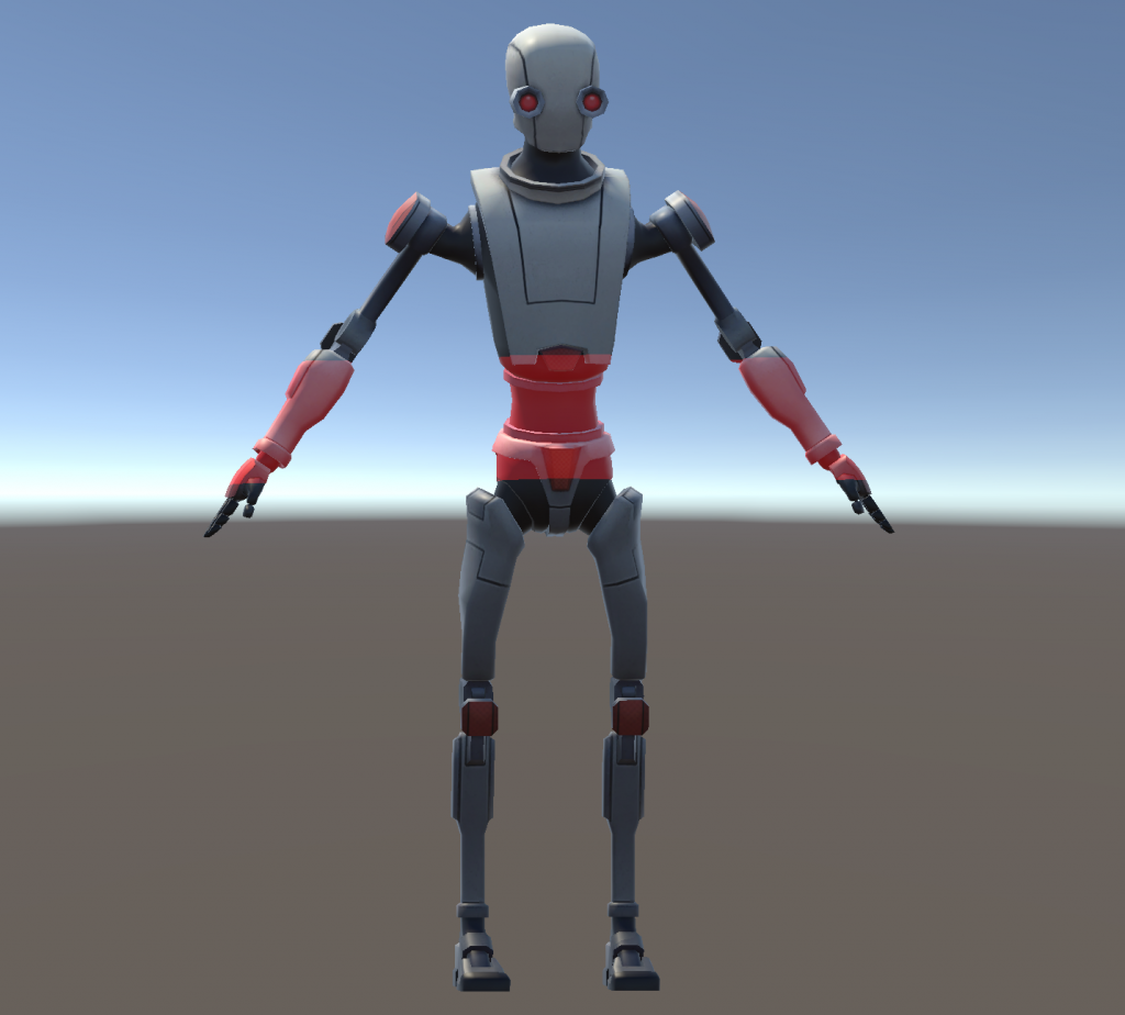
The final result will look like this:
In this part of the tutorial, we learned how we can manipulate pixel colors according to their coordinates, texture mapping and normal mapping. In the next part of this tutorial series, we are going to learn Time Node to animate shaders, transparency and difference between coordinate spaces.