
How to draw lines, circles or anything else using Line Renderer
Sometimes, you need to draw lines, circles or curves in your Unity games. In these cases, you can use Unity’s LineRenderer class. In this tutorial, we will see how we can draw lines, polygons, circles, wave functions, Bézier Curves. And also we will see how we can do a free drawing using Line Renderer in Unity3D. In order to see our other Unity tutorials, click here.
Line Renderer Component
To draw a line we have to add a LineRenderer component to a game object. Even if this component can be attached to any game object, I suggest you create an empty game object and add the LineRenderer to this object.
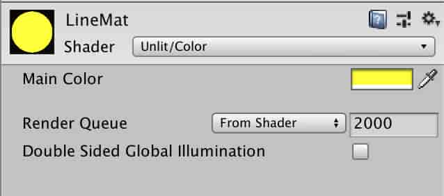
We need a material which will be assigned to LineRenderer. To do this create a material for the line in Project Tab. Unlit/Color shader is suitable for this material.
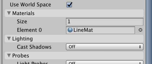
Assign LineMat material to the Line Renderer component.
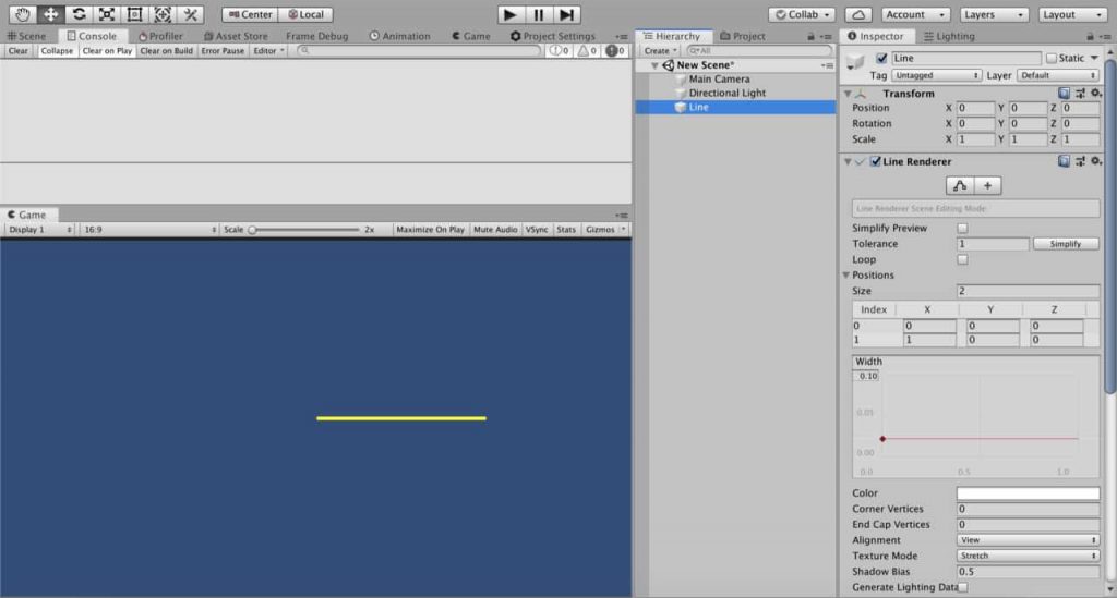
Line Renderer draws lines between determined positions. In other words, we tell the Line Renderer the points which will be connected and Line Renderer connects these points.
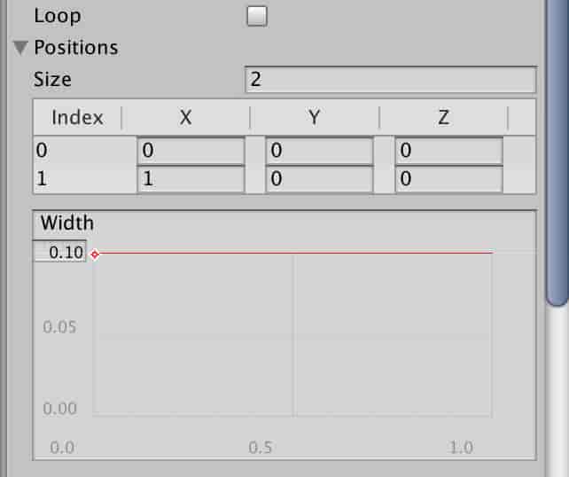
In the Positions section, you can change the number of points and positions of points. If you enter two different points, you will get a straight line. You can also change the width of the line in the section below.
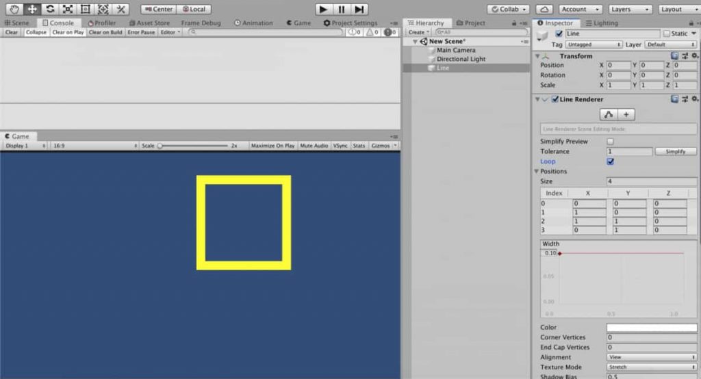
Likewise, two draw a triangle, you need 3 points and to draw a rectangle you need 4 points. Let’s draw a rectangle as an example.
To draw a rectangle, we need to set positions of 4 points. We also have to check the Loop toggle to obtain a closed shape.
Drawing Lines From C# Script
If we want to draw or control lines in real-time, we need to create a C# script. To draw lines from a script, we determine the size of position array and coordinates of positions in C# script. Therefore, LineRenderer can connect the points.
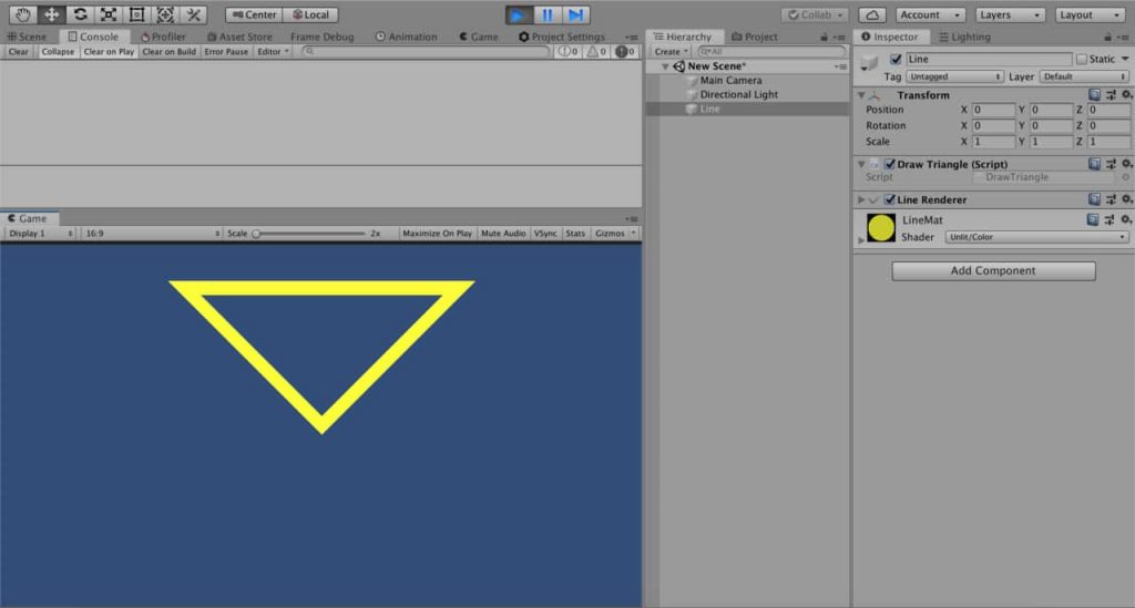
Let’s draw a triangle using a script as an example. First, create a script with the name “DrawScript”. And attach this script to a game object which already has a LineRenderer component.
public class DrawScript : MonoBehaviour
{
    private LineRenderer lineRenderer;

    void Start()
    {
        lineRenderer = GetComponent<LineRenderer>();
        Vector3[] positions = new Vector3[3] { new Vector3(0, 0, 0), new Vector3(-1, 1, 0), new Vector3(1, 1, 0) };
        DrawTriangle(positions);
    }

    void DrawTriangle(Vector3[] vertexPositions)
    {

        lineRenderer.positionCount = 3;
        lineRenderer.SetPositions(vertexPositions);
    }

}
This script will draw a triangle. Note that we already set the line width to 0.1 and checked the loop toggle, before. Therefore the same setting is also valid here.
We can also change the line width from the script using startWidth and endWidth. In addition to this, if you would like to change line width by position, you can set different values to them. In this case, Line Renderer will interpolate the line width according to position.
public class DrawScript : MonoBehaviour
{
    private LineRenderer lineRenderer;

    void Start()
    {
        lineRenderer = GetComponent<LineRenderer>();
        Vector3[] positions = new Vector3[3] { new Vector3(0, 0, 0), new Vector3(-1, 1, 0), new Vector3(1, 1, 0) };
        DrawTriangle(positions, 0.02f, 0.02f);
    }

    void DrawTriangle(Vector3[] vertexPositions, float startWidth, float endWidth)
    {
        lineRenderer.startWidth = startWidth;
        lineRenderer.endWidth = endWidth;
        lineRenderer.loop = true;
        lineRenderer.positionCount = 3;
        lineRenderer.SetPositions(vertexPositions);
    }

}
Drawing Regular Polygons and Circles
In this section, we are going to see how we can write a method that draws regular polygons. Since circles are n-gons which has big n, our function will be useful for circles also. But first, let me explain the mathematics behind it.
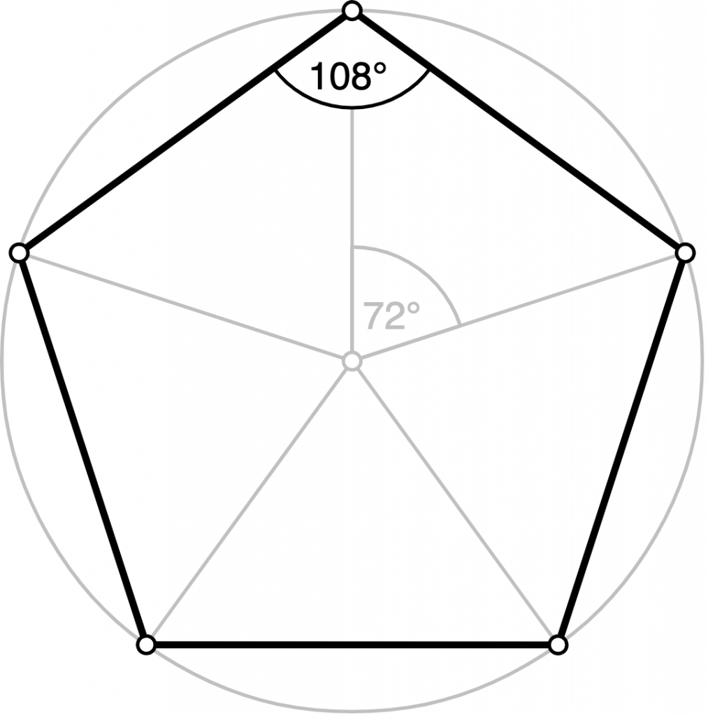
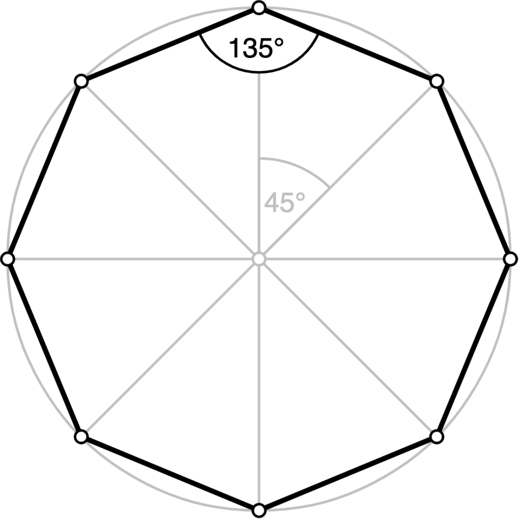
Vertices of regular polygons are on a circle. Also, the center of the circle and the center of the polygon are top of each other. The most reliable method to draw a polygon is to find the angle between successive vertices and locate the vertices on the circle. For instance, angle of the arc between successive vertices of a pentagon is 72 degrees or for an octagon, it is 45 degrees. To find this angle, we can divide 360 degrees(or 2xPI radians) with the number of vertices.
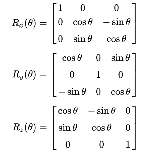
Then we need to find the positions of the vertices. To do this we assign an initial point for the first vertex and rotate this vertex for each vertex using a rotation matrix.
As you probably know, in order to rotate a point around an axis, we multiply the position vector of the point with the rotation matrix. Rotation matrices for rotations around x, y and z axes are given on the right.
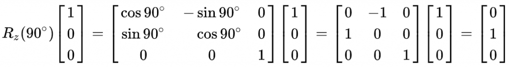
For example, when we want to rotate a point by 90 degrees around the z-axis, which has a coordinate (1,0,0), we multiply the position vector by a rotation matrix.
We need to construct a rotation matrix to rotate each vertex around the z-axis. Let’s me write our DrawPolygon method first and explain it.
void DrawPolygon(int vertexNumber, float radius, Vector3 centerPos, float startWidth, float endWidth)
{
    lineRenderer.startWidth = startWidth;
    lineRenderer.endWidth = endWidth;
    lineRenderer.loop = true;
    float angle = 2 * Mathf.PI / vertexNumber;
    lineRenderer.positionCount = vertexNumber;

    for (int i = 0; i < vertexNumber; i++)
    {
        Matrix4x4 rotationMatrix = new Matrix4x4(new Vector4(Mathf.Cos(angle * i), Mathf.Sin(angle * i), 0, 0),
                                                 new Vector4(-1 * Mathf.Sin(angle * i), Mathf.Cos(angle * i), 0, 0),
                                   new Vector4(0, 0, 1, 0),
                                   new Vector4(0, 0, 0, 1));
        Vector3 initialRelativePosition = new Vector3(0, radius, 0);
        lineRenderer.SetPosition(i, centerPos + rotationMatrix.MultiplyPoint(initialRelativePosition));

    }
}
You may wonder why the constructed rotation matrix is 4×4. In computer graphics, the 3-dimensional world is represented as 4-dimensional but this topic is not related to our business here. We just use it as if it is 3-dimensional.
We set the position of initial vertex and rotate it using rotationMatrix each time and add the center position to it.
The following image is an example of a hexagon which is drawn by this method.

If you increase the number of vertex points, this polygon turns to a circle.

Drawing Waves
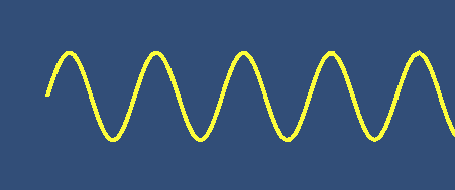
In this section, we are going to draw a sinusoidal wave, a traveling wave and a standing wave using sine function.
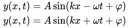
The mathematical function of the sine wave is given by the following:
where
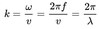
Here, k is wave number, f is frequency, ω is the angular frequency, λ is wavelength, v is the linear speed, t is the time and φ is the phase angle. We will not worry about the phase angle in our discussions.
Sine wave equation with a minus sign represents traveling wave from left to right and the equation with plus sign represents a traveling line wave right to left.
In order to draw a stable sinusoidal wave, we can drop the time part. The following method will draw a sine wave.
void DrawSineWave(Vector3 startPoint, float amplitude, float wavelength)
{
    float x = 0f;
    float y;
    float k = 2 * Mathf.PI / wavelength;
    lineRenderer.positionCount = 200;
    for (int i = 0; i < lineRenderer.positionCount; i++)
    {
        x += i * 0.001f;
        y = amplitude * Mathf.Sin(k * x);
        lineRenderer.SetPosition(i, new Vector3(x, y, 0) + startPoint);
    }
}
Our DrawSineWave method takes three parameters. They are startPoint which is for setting the start position in world space, amplitude which is for setting the amplitude of the wave and wavelength which is for setting the wavelength of the sine wave.
To obtain the positions of the corresponding mathematical function, first, we determine the positions on the x-axis. For each x, we have to calculate the y-position.
To animate this wave, we have to implement time to our function as follows:
void DrawTravellingSineWave(Vector3 startPoint, float amplitude, float wavelength, float waveSpeed){

    float x = 0f;
    float y;
    float k = 2 * Mathf.PI / wavelength;
    float w = k * waveSpeed;
    lineRenderer.positionCount = 200;
    for (int i = 0; i < lineRenderer.positionCount; i++){
        x += i * 0.001f;
        y = amplitude * Mathf.Sin(k * x + w * Time.time);
        lineRenderer.SetPosition(i, new Vector3(x, y, 0) + startPoint);
    }
}
This time we have four parameters. The fourth parameter is to set the wave speed. This wave travels to the left since we used plus sign in the function. If we would like to create a wave that travels to the right, we have to use the minus sign. You should keep in mind that we have to write this method in Update().
To create a standing wave, we have to add two waves which travel to the right and which travel to left.
void DrawStandingSineWave(Vector3 startPoint, float amplitude, float wavelength, float waveSpeed)
{

    float x = 0f;
    float y;
    float k = 2 * Mathf.PI / wavelength;
    float w = k * waveSpeed;
    lineRenderer.positionCount = 200;
    for (int i = 0; i < lineRenderer.positionCount; i++)
    {
        x += i * 0.001f;
        y = amplitude * (Mathf.Sin(k * x + w * Time.time) + Mathf.Sin(k * x - w * Time.time));
        lineRenderer.SetPosition(i, new Vector3(x, y, 0)+ startPoint);
    }
}
Drawing Bézier Curves
Bézier curves are parametric curves that are used to create smooth curved shapes. They are widely used in computer graphics. In this section, we are going to see how we can draw Bézier curves.
When a Bézier curve is controlled by 3 points, then it is called Quadratic Bézier Curve(the first equation below) and when it is controlled by 4 points, it is called Cubic Bézier Curve.


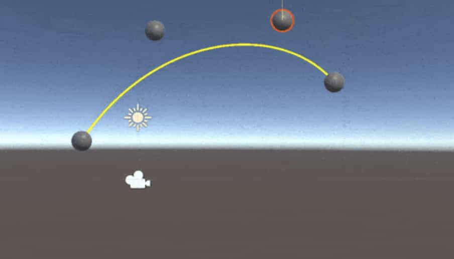
The following script will draw a quadratic Bézier curve using positions p0, p1, and p2. You should create three game objects and assign these objects to corresponding variables in the script to change the shape of the curve in real-time.
using System.Collections;
using System.Collections.Generic;
using UnityEngine;

public class BezierScript : MonoBehaviour
{
    private LineRenderer lineRenderer;
    public Transform p0;
    public Transform p1;
    public Transform p2;

    void Start()
    {
        lineRenderer = GetComponent<LineRenderer>();
    }

    void Update()
    {
        DrawQuadraticBezierCurve(p0.position, p1.position, p2.position);
    }

    void DrawQuadraticBezierCurve(Vector3 point0, Vector3 point1, Vector3 point2)
    {
        lineRenderer.positionCount = 200;
        float t = 0f;
        Vector3 B = new Vector3(0, 0, 0);
        for (int i = 0; i < lineRenderer.positionCount; i++)
        {
            B = (1 - t) * (1 - t) * point0 + 2 * (1 - t) * t * point1 + t * t * point2;
            lineRenderer.SetPosition(i, B);
            t += (1 / (float)lineRenderer.positionCount);
        }
    }
}
Likewise, the following method draws a cubic Bézier curve. This time we need 4 points.
void DrawCubicBezierCurve(Vector3 point0, Vector3 point1, Vector3 point2, Vector3 point3)
{

    lineRenderer.positionCount = 200;
    float t = 0f;
    Vector3 B = new Vector3(0, 0, 0);
    for (int i = 0; i < lineRenderer.positionCount; i++)
    {
        B = (1 - t) * (1 - t) * (1 - t) * point0 + 3 * (1 - t) * (1 - t) *
            t * point1 + 3 * (1 - t) * t * t * point2 + t * t * t * point3;

        lineRenderer.SetPosition(i, B);
        t += (1 / (float)lineRenderer.positionCount);
    }
}
Free Drawing using Line Renderer
In this section, we are going to see how we can draw freely using the mouse position. We can do this by creating a new game object with a line renderer attached. When we press the left mouse button, a new game object is created and each frame the position of the mouse added to the line renderer.
First of all, we need a prefab to create a new game object when we press the left mouse button. This is an empty game object with a line renderer component attached. In addition to this, do not forget to assign a material to the line renderer component. Create a prefab from this game object.
Second, create an empty game object and attach the following script DrawManager.
using System.Collections;
using System.Collections.Generic;
using UnityEngine;

public class DrawManager: MonoBehaviour
{
    private LineRenderer lineRenderer;
    public GameObject drawingPrefab;

    void Update()
    {
        if (Input.GetMouseButtonDown(0))
        {
            GameObject drawing = Instantiate(drawingPrefab);
            lineRenderer = drawing.GetComponent<LineRenderer>();
        }

        if (Input.GetMouseButton(0))
        {
            FreeDraw();
        }
    }

    void FreeDraw()
    {
        lineRenderer.startWidth = 0.1f;
        lineRenderer.endWidth = 0.1f;
        Vector3 mousePos = new Vector3(Input.mousePosition.x, Input.mousePosition.y, 10f);
        lineRenderer.positionCount++;
        lineRenderer.SetPosition(lineRenderer.positionCount - 1, Camera.main.ScreenToWorldPoint(mousePos));

    }
}
When you press the left mouse button, a new game object is instantiated from the prefab which we created before. We get the line renderer component from this game object. Then while we are pressing the left mouse button, we call FreeDraw() method.
In the FreeDraw method, we take x and y components of the mouse position and set the z-position as 10. Here, the mouse position is in the screen space coordinates. But we use world space coordinates in line renderer. Therefore we need to convert mouse position to world space coordinates. In each frame, we also need to increase the number of points. Since we do not know how many points we need, we cannot set position count before.
References
1-https://docs.unity3d.com/ScriptReference/LineRenderer.html
2-http://www.theappguruz.com/blog/bezier-curve-in-games
3-https://en.wikipedia.org/wiki/Bézier_curve
4-https://en.wikipedia.org/wiki/Sine_wave
Hey,
awesome tutorial. I’m pretty sure though that in the BezierCurve calculation it should say t += (1 / (float)(lineRenderer.positionCount-1));
otherwise t with the value 1 never gets applied to any position.
Cheers and thanks again. this really helped
Great tutorial!! thank you very much!!
Great tutorial thanks! I would like to draw a circle on the ground, viewed from above. How would I change the matrix to accomplish this?
You need to use the rotation matrix that is given as Ry, above. Do not forget to add 4th row and column which are (0,0,0,1)
Merhabalar,
FreeDrawing kodunun aynısını yazmama rağmen çizilen ilk çizgi mouse position yerine 0,0,0 noktasından çıkıyor sorun ne olabilir acaba? Birde line renderer a 3D collider nasıl ekleyeceğiz ?
Merhaba, muhtemelen eklemiş olduğunuz line renderer komponentinin üzerinde ön tanımlı gelen position count değerini ve ön tanımlı noktaları olduğu gibi kullanıyorsunuz. Inspector’daki position count değerini 0 olarak belirleyip, öyle deneyin.
Collider eklemenin bir yolu, her iki noktanın ortasında(çizgi segmenti diyelim) box collider atanmış bir prefab yaratıp, çizgi segmentinin yatayla yaptığı açıyı hesaplayıp, box collider atanmış, yeni yaratılan game objectin açısını buna ayarlamak. Segmentin yatayla yaptığı açıyı bulmak için çizgi segmentini oluşturan iki uç noktayı vektörel olarak birbirinden çıkarın. Elde ettiğiniz vektörün x ekseni üzerindeki birim vektörle yaptığı açıyı Vector3.Angle() metodunu kullanarak hesaplayabilirsiniz.
Collider eklemeyle ilgili çok talep geliyor. Önümüzdeki dönemler zamanım elverirse yazıyı bunu göz önüne alarak genişletmeyi düşünüyorum.
Hi,
In the circle, if i create a circle with radius 1. This is like 1 meter or 1 cm?
Hi,
Predefined gravity in Unity is -9.81 units/s^2. If you have not changed this, you should think 1 Unity Unit=1 Meter.
Hi, i saw this is in unity forums, but i didn’t get it.
What is exactly 1 Unity Unit?
It is equal to 1 meter.
yes xD, but 1 Unit is like a float?
Do you ask the definition of the term “unit”? If so, you should take a look at basic maths or physics books. If you ask which data type you should use for the radius, you should use float.
Hi, thx.
Jsut one more question, when i draw a circle with a radius less or equal than 0.05, only appears half of a circle. Why?
I checked and it seems fine. Did you try to set the linewidth smaller than the radius?
Yes, i use this: DrawPolygon(360, 0.05f, new Vector3(0, 0, 0), 0.01f, 0.01f);
half of the circle is visible the other half is “reversed” like what happends with Panel ( you can only see form one side)
I have not time to check but it can be about the precision of floating-point numbers. 360 vertex points are meaningless, you cannot distinguish much smaller vertex numbers while creating a circle.
Yes, this solve the problem! thanks a lot 🙂
For people with the same problem reduce the number of points
I tried the free drawing tutorial in unity 2019.3.5f1. While instantiating the prefab, the new line is get attached to the last line.
I did not understand the problem exactly. Unity is making the new prefab the child of the last game object, right?
how can we achieve this kind of effect: https://www.youtube.com/watch?v=UfQ0UMXbFmg with line renderer.
I haven’t tried but I think you can achieve similar results by creating relatively long wavelength standing waves from knee point to two ends.
Welp this is a great tutorial!
I actually came across here because i wanted to create a dashed line, and perhaps animate it so the dots would be moving. I want to make some kind of a trade route indicator. I was however unsuccesful in having the linerenderer render the texture properly. Tiled mode kinda seemed to work, then messing with the parameters of a unlit shader got me a decent looking line, but those were only good once, and now for subsequently drawn lines.
Perhaps a good next tutorial is the texturing of a linerender? like drawing dots, spacing it out etc.
Hey, thank you for your feedback. In the future, I may extend the article with different examples like dashed lines or animation. For now, let me explain how to make a dashed line briefly.
The best method is to add Texture Shader to your line material(If you want it to have transparency between dots, it has to be transparent shader as well). Then you have to access material properties and using mainTextureScale property you should set the tiling every time. In order to find the tiling value, you should divide the physical length(not length of the position list) of the line to a scale value which you can edit from the inspector.
This is for a line that has only two points.
public class DashedLine : MonoBehaviour
{
LineRenderer lineRenderer;
Renderer rend;
public float dashLength=1f;
public float animationSpeed = 1f;
void Start()();();
{
lineRenderer = GetComponent
rend = GetComponent
}
// Update is called once per frame
void Update()
{
rend.material.mainTextureScale = new Vector2(Vector3.Distance(lineRenderer.GetPosition(0), lineRenderer.GetPosition(1)) / dashLength, 0.15f);
rend.material.mainTextureOffset = new Vector2(Time.time*animationSpeed, 0f);
}
}